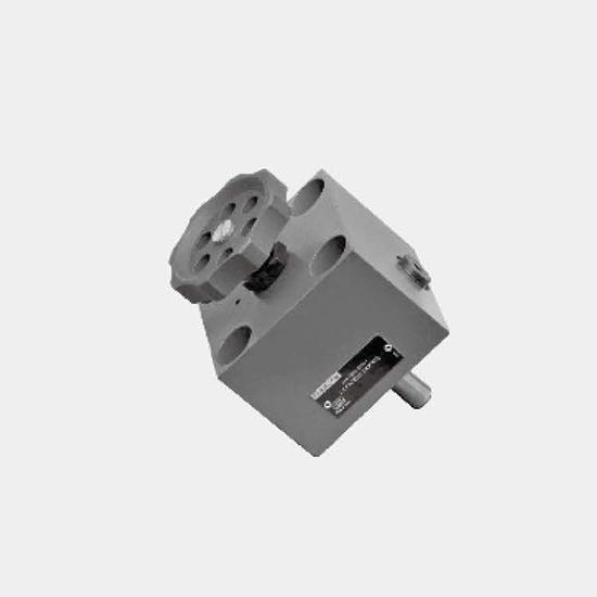
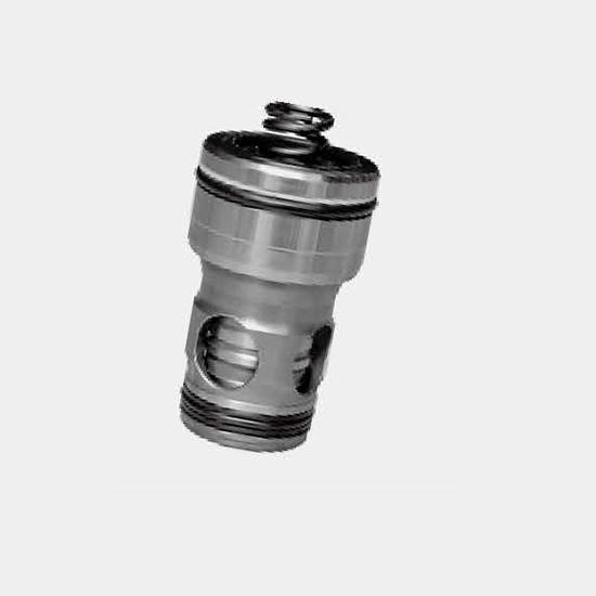
Function and configuration2-way cartridge valves are designed as inserts for compact manifold control blocks. The installation hole dimension of the control block fitting the main valve component with...
Product Detail
Function and configuration
2-way cartridge valves are designed as inserts for compact manifold control blocks. The installation hole dimension of the control block fitting the main valve component with ports A and B is in accord with ISO 7368 and sealed with a cover. In most cases, the cover also acts as a connection between the control side of the main component and the pilot valves. By controlling the main valve with suitable pilot valves, the main component can assume pressure, directional or throttling functions, or their combination.
Particularly economic designs can be achieved by matching the valve sizes to the individual actuator. When the element on the main valve is able to assume more than one function, a particularly economic design can be achieved.
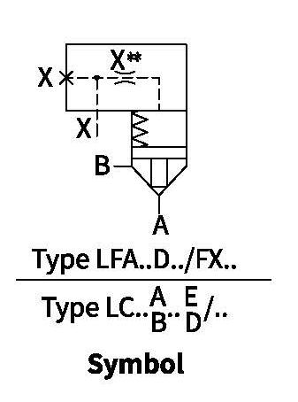
Directional function:
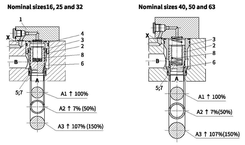
2-way cartridge valves basically comprise of control cover (1) and cartridge element (2). The control cover contains the control holes, and optional stroke limiter depending on the function, a hydraulically controlled directional poppet valve or a shuttle valve. In addition, directional spool valves or directional poppet valves may be mounted onto the control cover. The cartridge element basically comprises of a sleeve (3), an adjustment ring (4) (only up to NG32), valve poppet (5), optionally with damping nose (6), or without damping nose (7), and return spring (8).
Function:
Operation of 2-way cartridge valves depends on pressure. Hence for operation, there are three important pressure-bearing areas: A1, A2, A3. The area A1 on valve seat is taken as 100%. The annular area A2 is 7% or 50% of area A1 depending on the model. The area ratio A1:A2 is, therefore either 14.3:1 or 2:1. Area A3 is equal to sum of areas A1+A2. Due to the different area ratios A1:A2 and consequently the different annulus area (A2), area A3 may be either 107% or 150% of the 100% area at seat A1.
Basic application :
Areas A1 and A2 operate to open the valve. Area A3 and the spring operates to close the valve. The effective direction of the resultant force (of opening and closing forces) determines the switched position of the 2-way cartridge valve.
2-way cartridge valves may have flow passed from A to B or from B to A. When pilot oil acting on area A3 is from port B or supply from an external pilot oil, port A is closed, and leakage-free.
Function and configuration
Technical data
| Max.operating pressure | Without bar directional valve | 420 |
| - Port A, B,X,Z1,Z2 bar | 315; 350; 420 (according to the maximum operating pressure of built-on valves) | |
| -Port Y bar | Corresponds to the tank pressure of the built-on valve | |
| Fluid | Mineral oil suitable for NBR and FKM seal | |
| Phosphate ester for FKM seal | ||
| Fluid temperature range ℃ | -30 to +80 (NBR seal) | |
| -20 to+80 (FKM seal) | ||
| Viscosity range m㎡/s | 2.8 to 380 | |
| Degree of contamination | Maximum permissible degree of fluid contamination: Class 9. NAS 1638 or 20/18/15, ISO4406 1) | |
For applications outside these parameters, please consult us!
1) To prevent the problem caused by fluid contamination, fluid cleanliness mentioned above must be met.
Unit dimensions
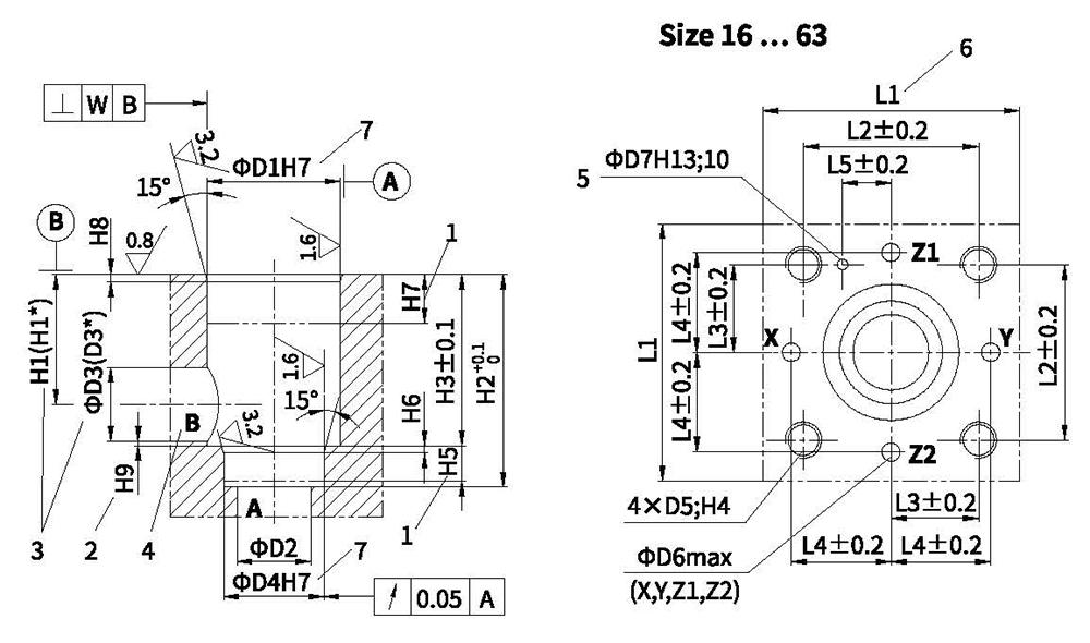
Mounting cavity and connection dimensions to DIN ISO 7368
1 Depth offit
2 Controldimension
3 If the diameter for port B is a different one than.D3 or (.D3*),the distance from the cover contact surface to the center of the bore must be calculated.4 Port B may be positioned around the central axis of port A.However, it must be ensured that the mounting bores and the control bores are not damaged.5 Bore for locating pin
6 80 mm only with control cover for directional valve set-up size 16 (axis X-Y bores)7 For 0D ≤45mm -> fit H8is admissible
Unit dimensions
Installation bore and connection dimensions according to ISO 7368
| 通径 | 16 | 25 | 32 | 40 | 50 | 63 |
| ΦD1 | 32 | 45 | 60 | 75 | 90 | 120 |
| ΦD2 | 16 | 25 | 32 | 40 | 50 | 63 |
| ΦD3 | 16 | 25 | 32 | 40 | 50 | 63 |
| (ΦD3*) | 25 | 32 | 40 | 50 | 63 | 80 |
| ΦD4 | 25 | 34 | 45 | 55 | 68 | 90 |
| ΦD5 | M8 | M12 | M16 | M20 | M20 | M30 |
| Φ D61) | 4 | 6 | 8 | 10 | 10 | 12 |
| ΦD7 | 4 | 6 | 6 | 6 | 8 | 8 |
| H1 | 34 | 44 | 52 | 64 | 72 | 95 |
| (H1*) | 29.5 | 40.5 | 48 | 59 | 65.5 | 86.5 |
| H2 | 56 | 72 | 85 | 105 | 122 | 155 |
| H3 | 43 | 58 | 70 | 87 | 100 | 130 |
| H4 | 20 | 25 | 35 | 45 | 45 | 65 |
| H5 | 11 | 12 | 13 | 15 | 17 | 20 |
| H6 | 2 | 2.5 | 2.5 | 3 | 3 | 4 |
| H7 | 20 | 30 | 30 | 30 | 35 | 40 |
| H8 | 2 | 2.5 | 2.5 | 3 | 4 | 4 |
| H9 | 0.5 | 1 | 1.5 | 2.5 | 2.5 | 3 |
| L1 | 65/80 | 85 | 102 | 125 | 140 | 180 |
| L2 | 46 | 58 | 70 | 85 | 100 | 125 |
| L3 | 23 | 29 | 35 | 42.5 | 50 | 62.5 |
| L4 | 25 | 33 | 41 | 50 | 58 | 75 |
| L5 | 10.5 | 16 | 17 | 23 | 30 | 38 |
| W | 0.05 | 0.05 | 0.1 | 0.1 | 0.1 | 0.2 |
Note: " Maximum dimension
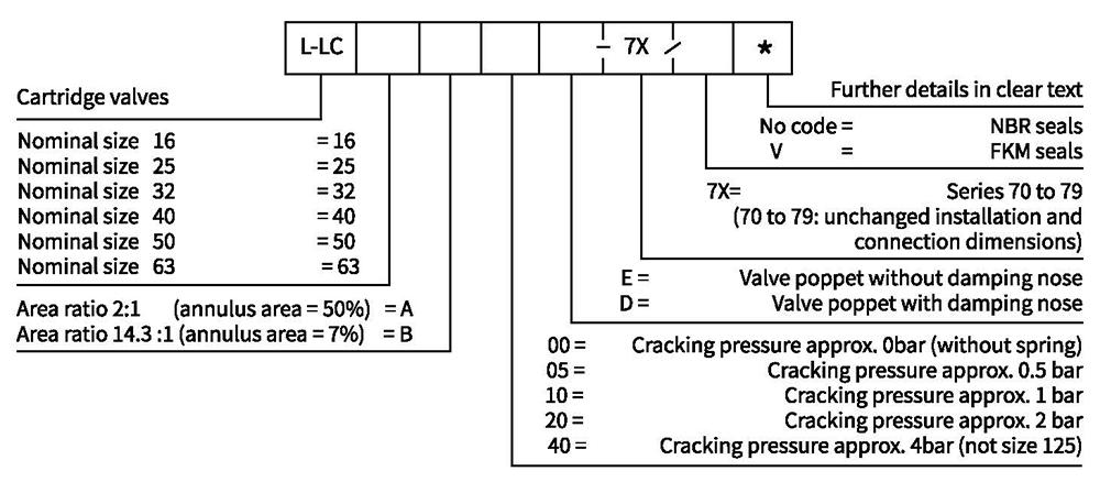
Ordering code
· Cartridge valves (without control cover)
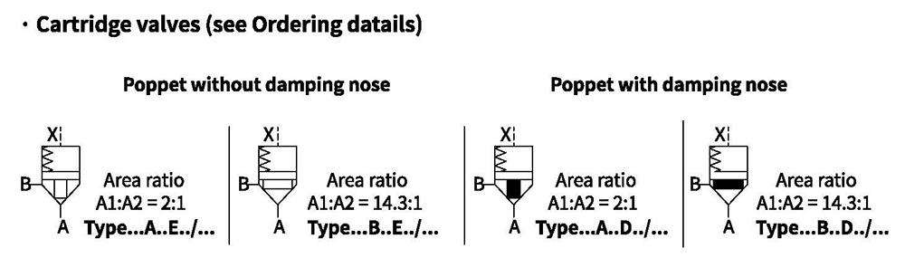
Symbols
Technical data
. 2-way cartridge valves directional
| Area | Version | Size | |||||
| 16 | 25 | 32 | 40 | 50 | 63 | ||
| A1 c㎡ | LC..A.. | 1.89 | 4.26 | 6.79 | 11.1 | 19.63 | 30.2 |
| LC..B.. | 2.66 | 5.73 | 9.51 | 15.55 | 26.42 | 41.28 | |
| A2 c㎡ | LC..A.. | 0.95 | 1.89 | 3.39 | 5.52 | 8.64 | 14 |
| LC..B.. | 0.18 | 0.43 | 0.67 | 1.07 | 1.85 | 2.90 | |
| A3 c㎡ | LC..A.. | 2.84 | 6.16 | 10.18 | 16.62 | 28.27 | 44.2 |
| LC..B.. | 2.84 | 6.16 | 10.18 | 16.62 | 28.27 | 44.2 | |
| Stroke cm | LC..E.. | 0.9 | 1.17 | 1.4 | 1.7 | 2.1 | 2.3 |
| LC..D.. | 0.9 | 1.17 | 1.4 | 1.9 | 2.3 | 2.8 | |
| Pilot volume cm | LC..E.. | 2.56 | 7.21 | 14.3 | 28.3 | 59.4 | 102 |
| LC..D.. | 2.56 | 7.21 | 14.3 | 31.6 | 65.0 | 124 | |
| Theoretical1) pilot fow (L/min) | LC..E.. | 15.4 | 43.3 | 86 | 170 | 356 | 612 |
| LC..D.. | 15.4 | 43.3 | 86 | 190 | 390 | 744 | |
| Weight kg | cartridge valves L-LC | 0.25 | 0.5 | 1.1 | 1.9 | 3.9 | 7.2 |
| Cracking pressure (bar) Direction of fow: Ato B | LC..A00.. | 0.02 | 0.02 | 0.05 | 0.05 | 0.05 | 0.07 |
| LC..A 05.. | 0.35 | 0.35 | 0.36 | 0.35 | 0.37 | 0.31 | |
| LC..A 10.. | 0.70 | 0.68 | 0.72 | 0.71 | 0.67 | 0.64 | |
| LC..A 20.. | 2.03 | 2.18 | 2.12 | 2.02 | 2.01 | 2 | |
| LC..A 30.. | - | - | - | - | - | - | |
| LC..A 40.. | 3.50 | 3.90 | 3.80 | 4.0 | 4.11 | 3.8 | |
| LC..B 00.. | 0.01 | 0.02 | 0.04 | 0.04 | 0.04 | 0.05 | |
| LC..B 05.. | 0.25 | 0.26 | 0.26 | 0.25 | 0.28 | 0.23 | |
| LC.,B 10.. | 0.49 | 0.50 | 0.51 | 0.51 | 0.48 | 0.47 | |
| LC..B 20.. | 1.44 | 1.62 | 1.52 | 1.44 | 1.5 | 1.5 | |
| LC..B 30.. | - | - | - | - | - | - | |
| LC..B 40.. | 2.48 | 2.90 | 2.70 | 2.86 | 3.05 | 2.8 | |
| Cracking pressure (bar) Direction of fow: Bto A | LC..A 00.. | 0.04 | 0.05 | 0.1 | 0.1 | 0.1 | 0.14 |
| LC..A 05.. | 0.69 | 0.78 | 0.72 | 0.7 | 0.84 | 0.68 | |
| LC..A10.. | 1.38 | 1.53 | 1.42 | 1.43 | 1.47 | 1.37 | |
| LC..A 20.. | 4.05 | 4.91 | 4.25 | 4.06 | 4.57 | 4.33 | |
| LC..A 30.. | - | - | - | - | - | - | |
| LC..A 40.. | 6.96 | 8.74 | 7.6 | 8.05 | 9.34 | 8.15 | |
| LC..B 00.. | 0.24 | 0.25 | 0.5 | 0.5 | 0.5 | 0.8 | |
| LC..B 05.. | 3.69 | 3.4 | 3.64 | 3.64 | 3.95 | 3.27 | |
| LC..B 10.. | 7.43 | 6.69 | 7.24 | 7.37 | 6.88 | 6.62 | |
| LC..B 20.. | 21.3 | 21.5 | 21.6 | 20.9 | 21.4 | 20.9 | |
| LC..B 30.. | - | - | - | - | - | - | |
| LC..B 40.. | 36.6 | 38.3 | 38.6 | 41.5 | 43.6 | 39.4 | |
For applications outside these parameters, please consult us!
1)Theoretical pilot flow to achieve a switching time of 10 ms.
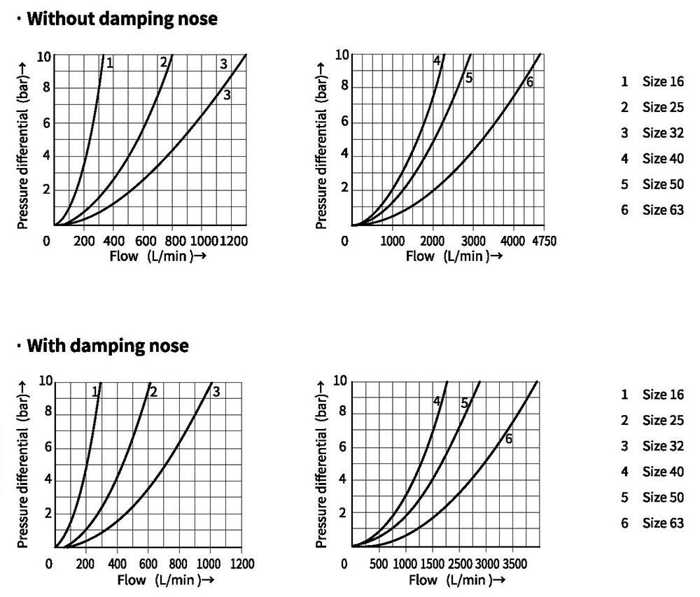
Characteristic curves (Measured at oil=40°C +5°C,using HLP46)
 11
Dimension of O-rings for Cartridge valve type L-LC
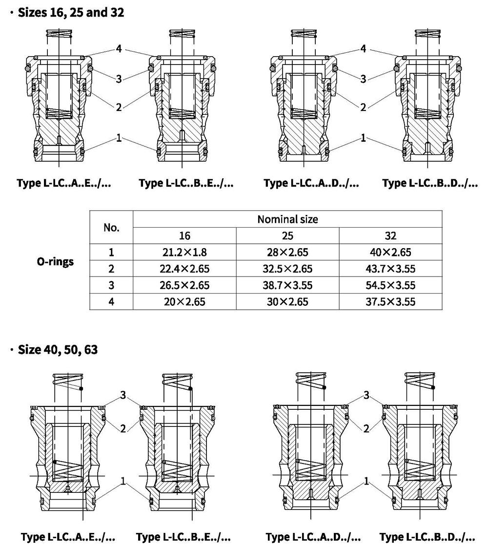
| No. | Nominal size | ||
| 40 | 50 | 63 | |
| 1 | 48.7x3.55 | 61.5x3.55 | 80x5.3 |
| 2 | 69x3.55 | 80x5.3 | 109x5.3 |
| 3 | 67x3.55 | 77.5x5.3 | 106x5.3 |
Fixing screws
Internal hexagon according to GB/T 70.1-10.9 (Included in supply list)
| Size | Type of control covers | Dimension | QTY | Tighting torque MA (Nm) | Nominal size | Type of control covers | Dimension | QTY | Tighting torque MA (Nm) |
| 16 | D | M8x40 | 4 | 32 | 40 | D | M20x70 | 4 | 520 |
| G | M8x40 | G | M20x70 | ||||||
| GWA, GWB | M8x45 | GWA, GWB | M20x70 | ||||||
| H1,H2 | M8x40 | H1,H2 | M20x110 | ||||||
| R,RF | M20x70 | ||||||||
| KWA, KWB | M8x45 | KWA, KWB | M20x70 | ||||||
| WEA,WEB | M8x45 | WEA, WEB | M20x70 | ||||||
| WECA | M8x40 | WECA | M20x70 | ||||||
| WEMA, WEMB | M8x70 | WEMA,WEMB | M20x70 | ||||||
| 25 | D | M12x50 | 4 | 110 | 50 | D | M20x80 | 4 | 520 |
| G | M12x50 | G | M20x80 | ||||||
| GWA, GWB | M12x50 | GWA,GWB | M20x80 | ||||||
| H1,H2 | M12x50 | H2 | M20x120 | ||||||
| R,RF | M12x50 | R,RF | M20x80 | ||||||
| KWA, KWB | M12x50 | KWA, KWB | M20x80 | ||||||
| WEA, WEB | M12x50 | WEA, WEB | M20x80 | ||||||
| WECA | M12x50 | WECA | M20x80 | ||||||
| WEMA, WEMB | M12x50 | WEMA, WEMB | M20x80 | ||||||
| 32 | D,G,R,RF GWA,GWB, KWA, KWB, WEA,WEB, WECA, WEMA,WEMB | M16x60 | 4 | 270 | 63 | D,G,R,RF GWA, GWB, KWA, KWB, WEA,WEB, WECA, WEMA,WEMB | M30x100 | 4 | 1800 |
| H1,H2 | M16x80 | H2 | M30x150 |
Control covers with remote control
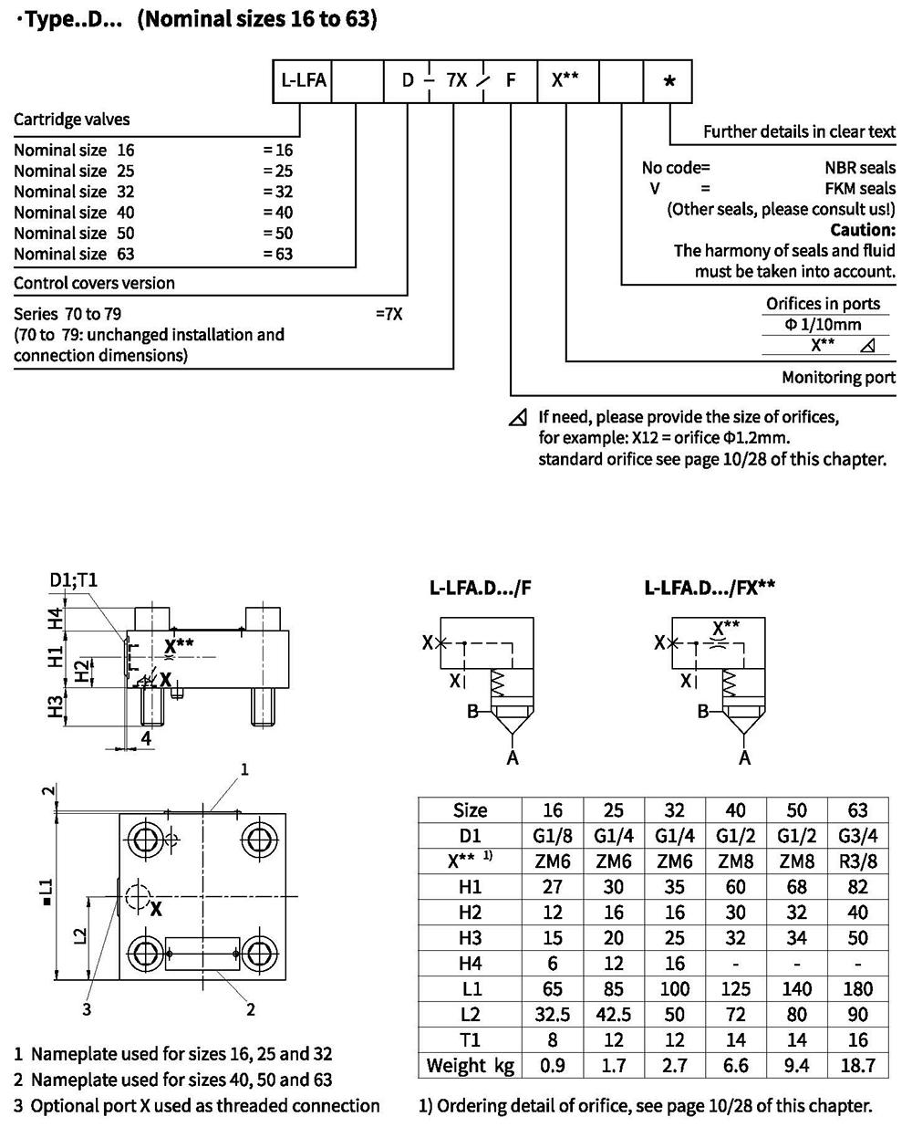
Control covers with stroke limiter and remote control
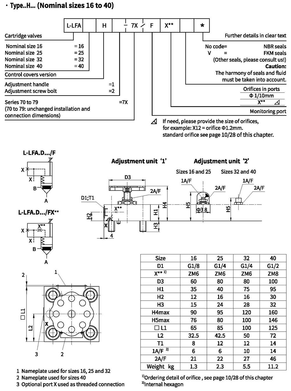
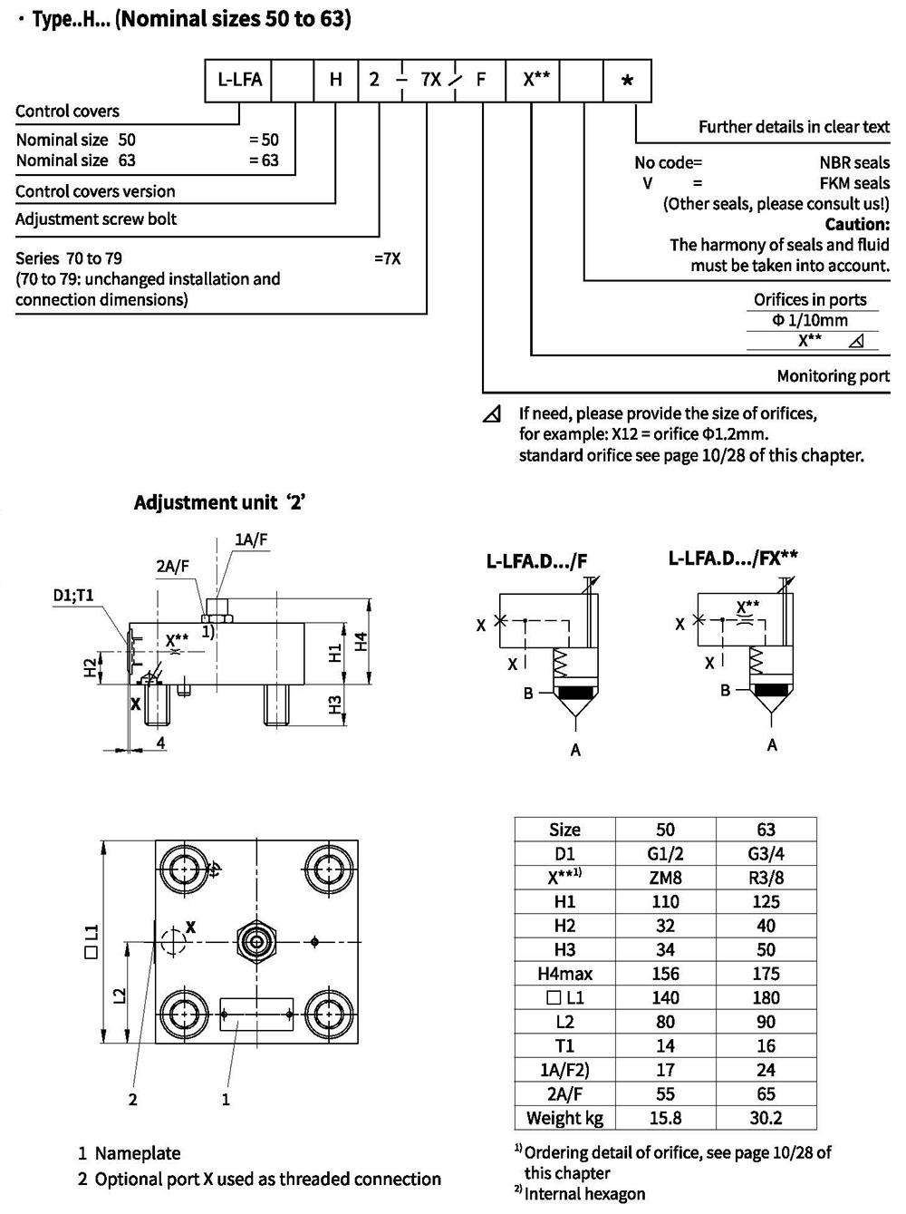
Control covers with stroke limiter and remote control
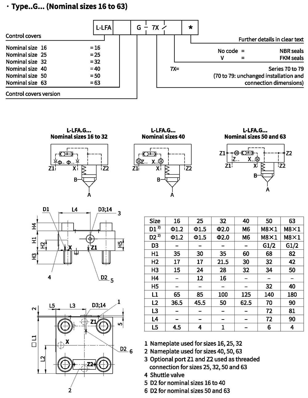
Control cover with built-in shuttle valve
Control cover with built-in directional poppet valve
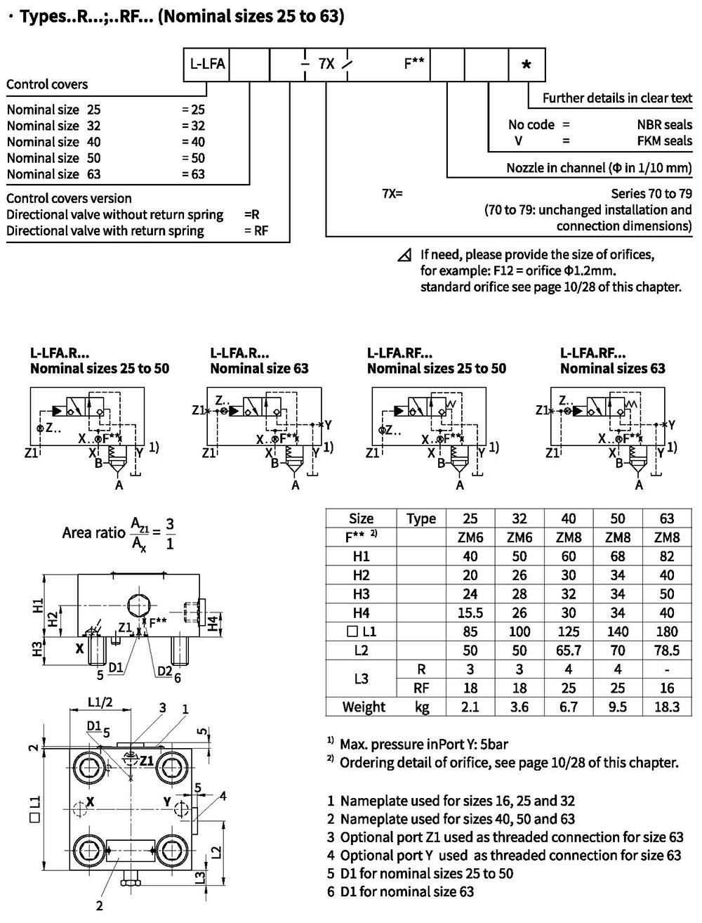
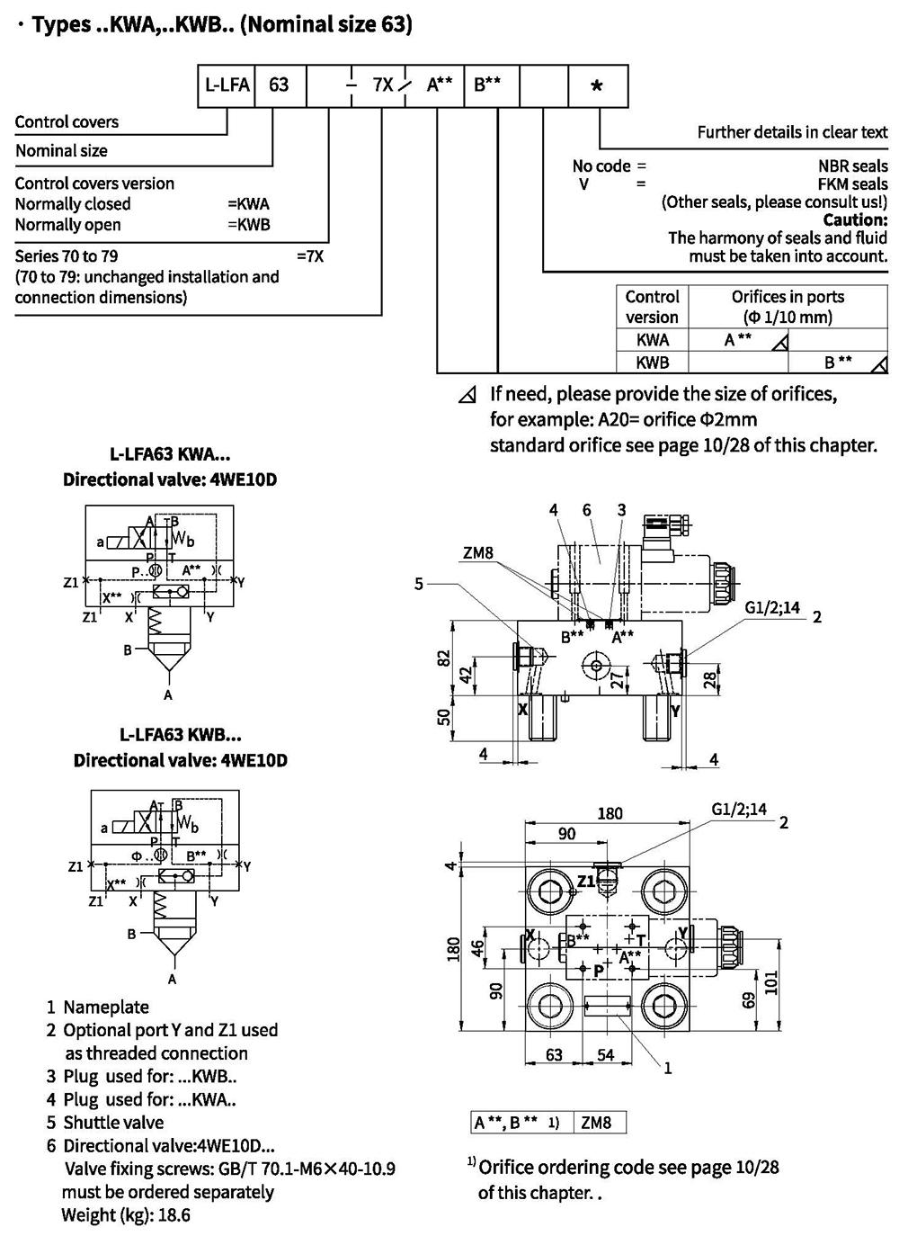
Control cover for mounting directional spool or directional poppet valve
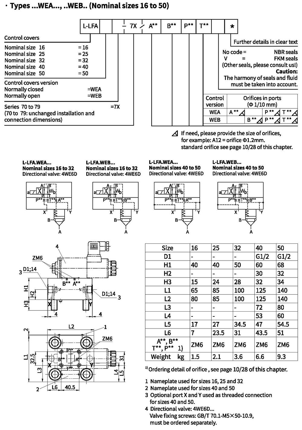
Control cover for mounting directional spool or directional poppet valve
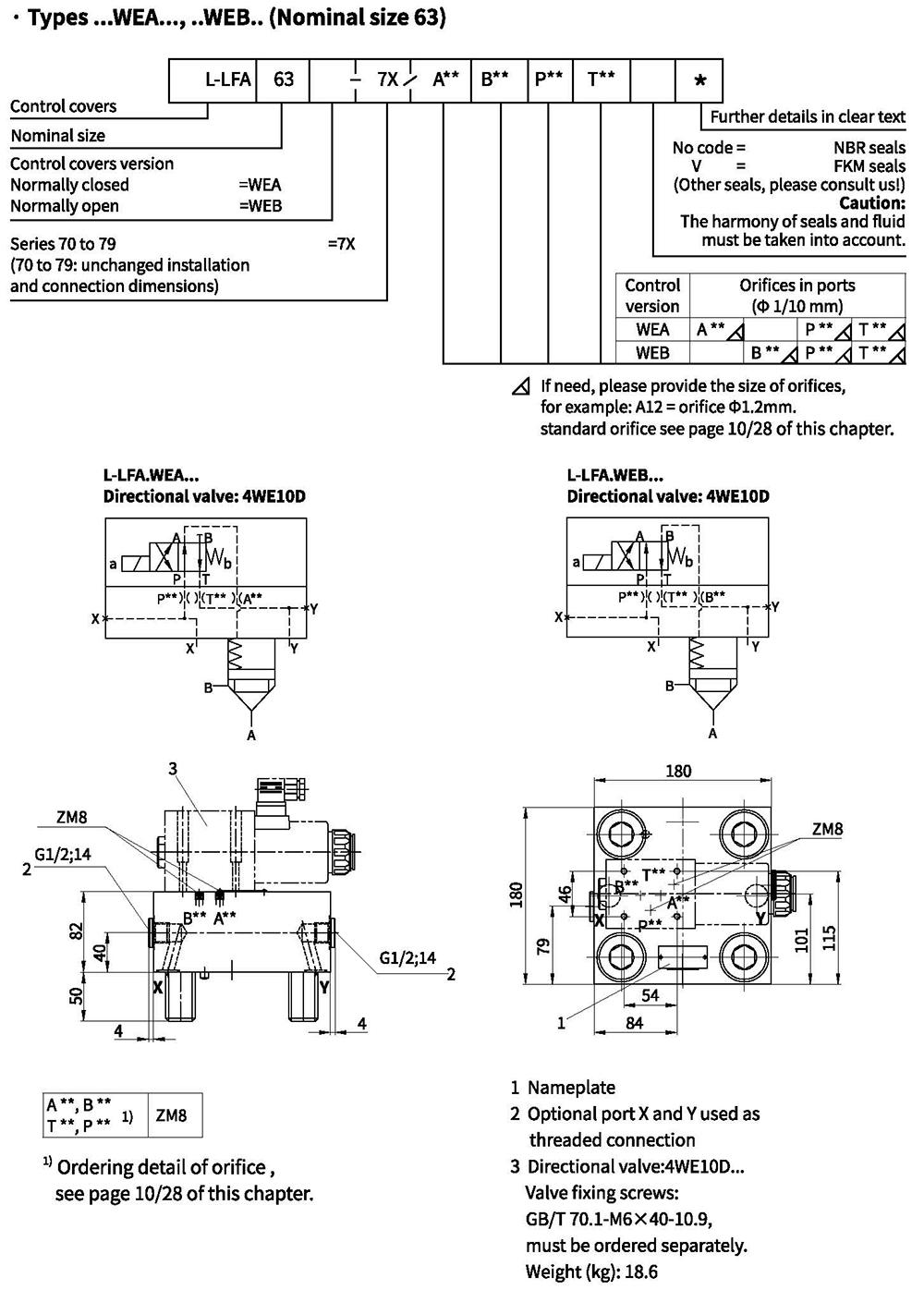
Control cover for mounting directional spool or directional poppet valve
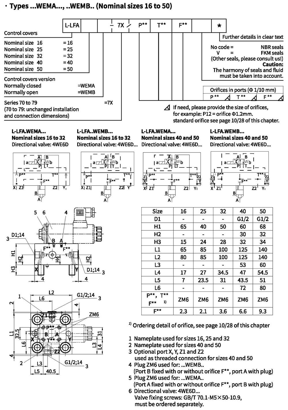
Control cover for mounting directional spool or directional poppet valve
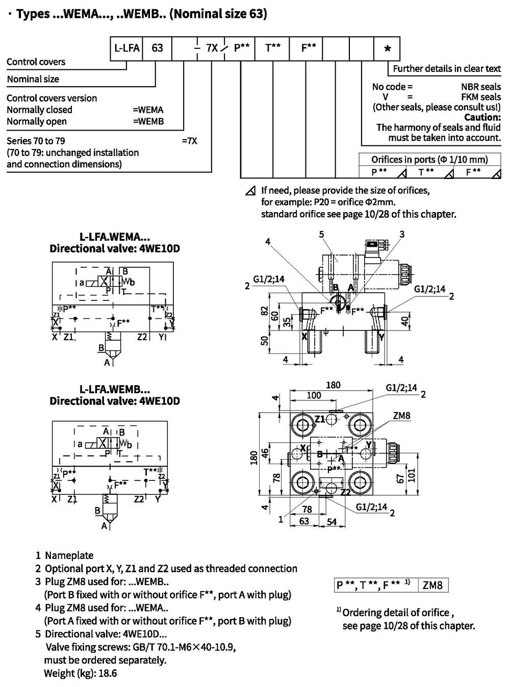
Control cover for mounting directional spool valve
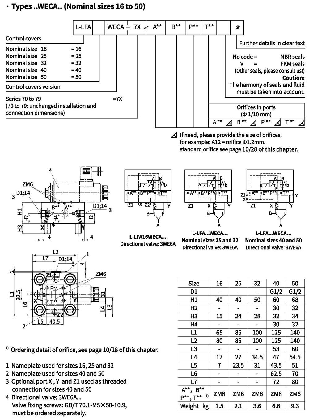
Control cover for mounting directional spool valve
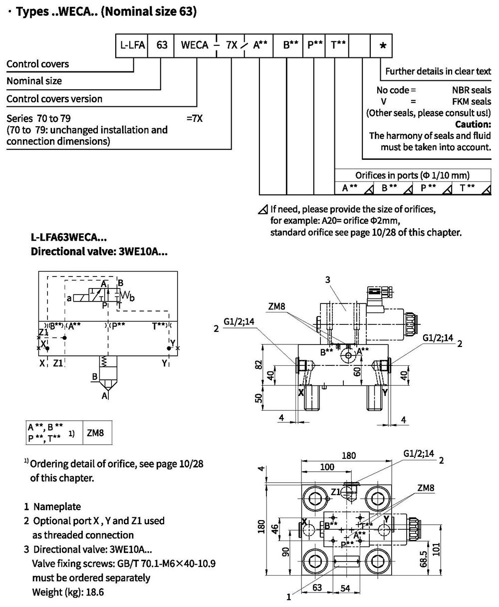
Control cover for mounting directional spool or poppet valve
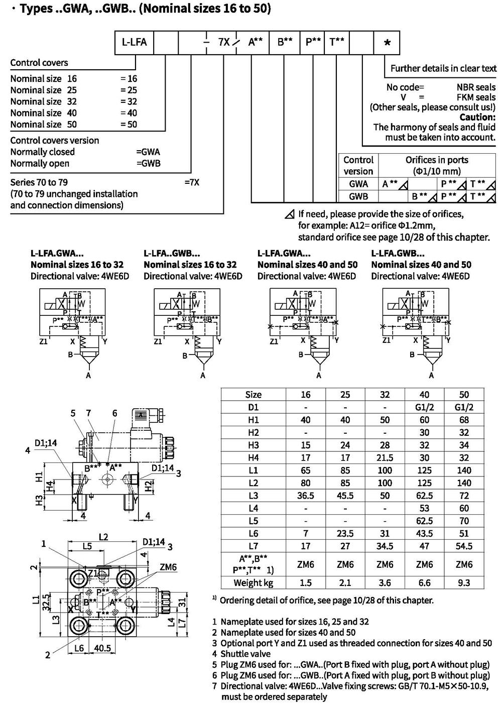
Control cover for mounting directional spool or poppet valve
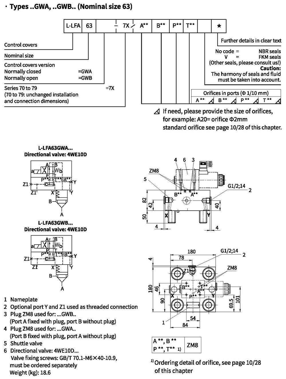
Control cover for mounting directional spool or poppet valve
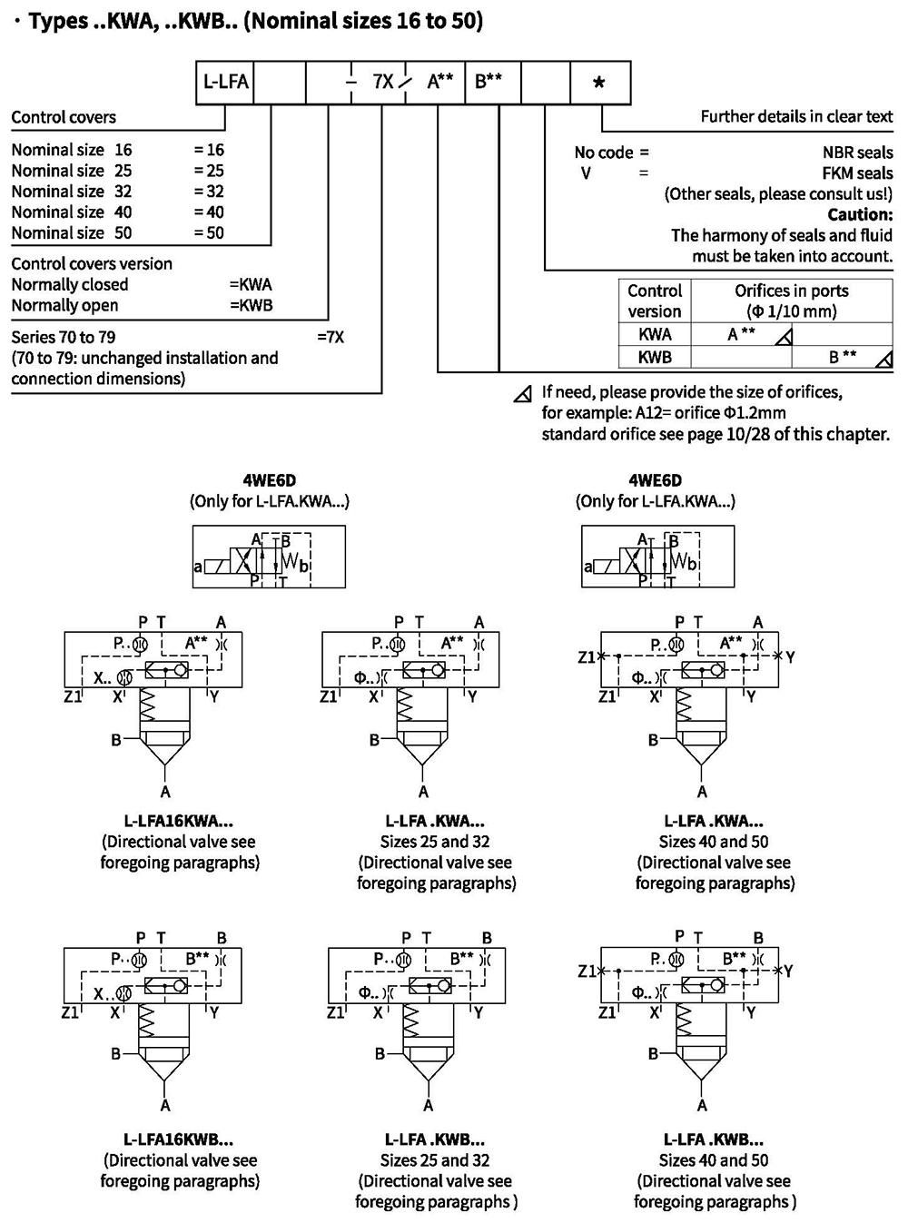
Control cover for mounting directional spool or poppet valve
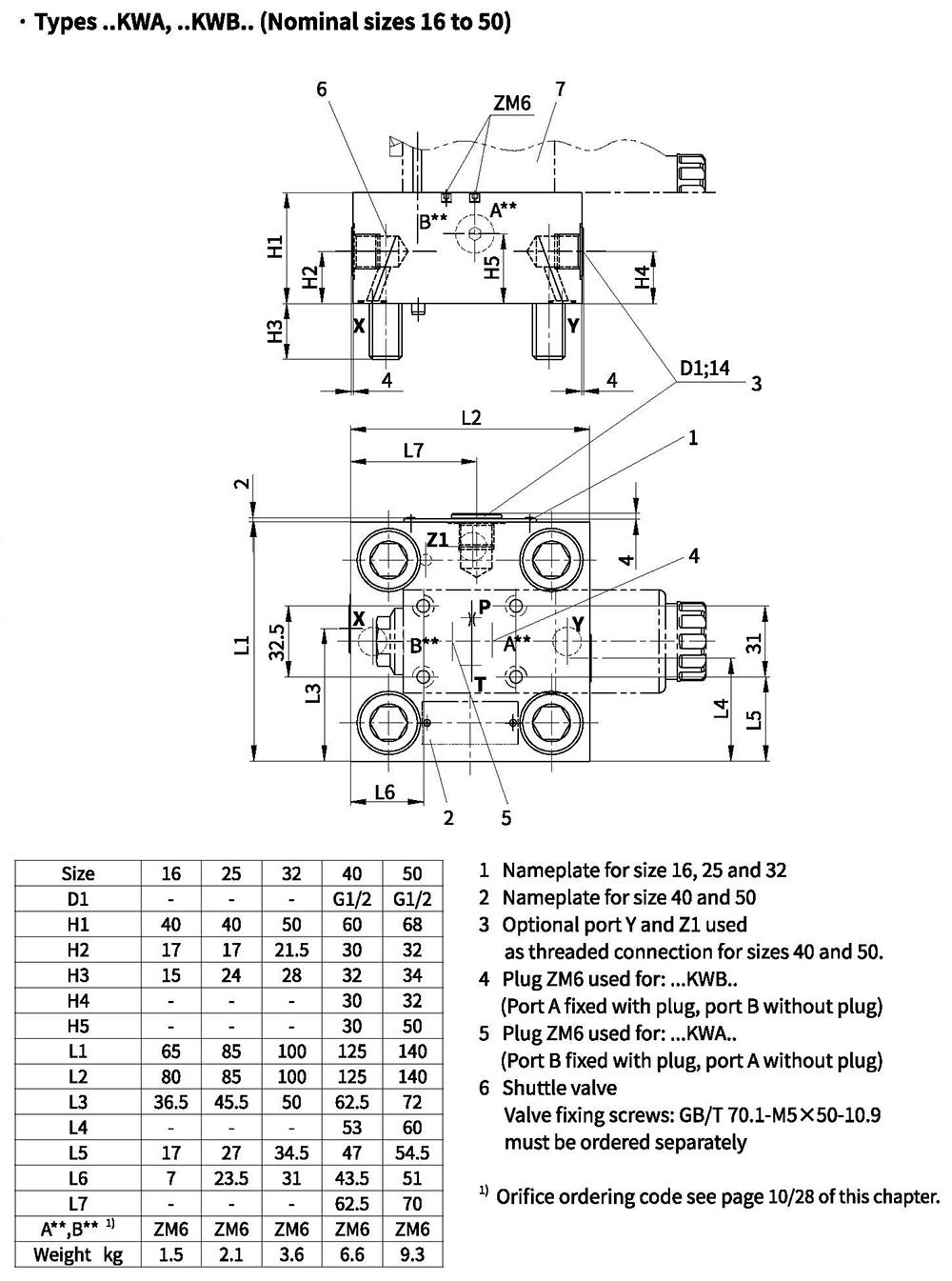
Control cover for mounting directional spool or poppet valve