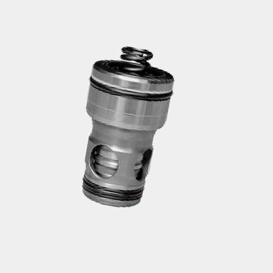
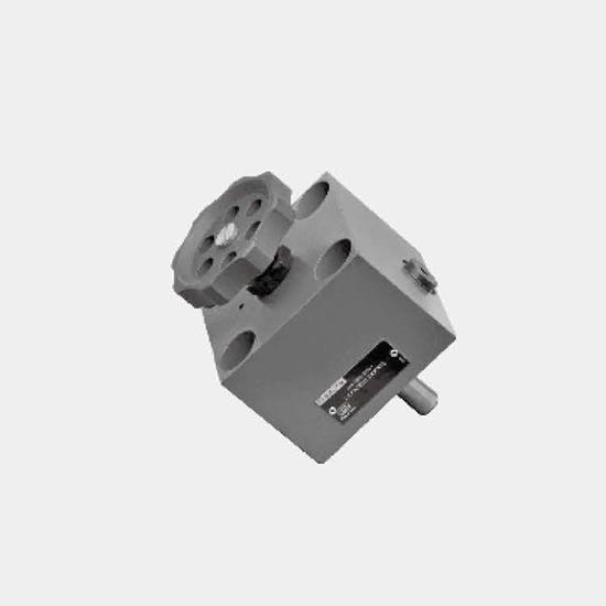
Function, section and symbolGeneralThe 2-way cartridge valves for pressure control functions are pilot operated poppet or spool valves. The main component designed as a cartridge valve (1) is inserted...
Product Detail
Function, section and symbol
General
The 2-way cartridge valves for pressure control functions are pilot operated poppet or spool valves. The main component designed as a cartridge valve (1) is inserted in a hole bore standardized to DIN ISO 7368 and is sealed by control cover (2).
The pilot valve (4) is integrated into the control cover (2) or mounted onto the control cover as a pilot valve with interface connections to DIN 24 340 (2). Different pressure functions can be realized by combining the cartridge valve with the control covers.
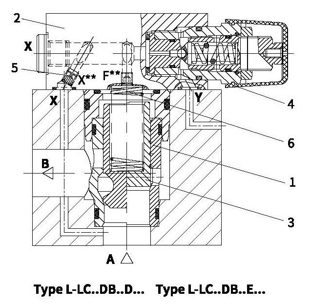
Pressure relief function
Control cover type L-LFA..DB...
Cartridge valve type L-LC..DB...
The cartridge valve (1) for the pressure relief function (type L-LC . DB...) is a poppet valve with a area ratio of 1:1(no effective area at port B). The pressure acting at port A is fed via the pilot oil supplying orifice (5) to the main spring chamber (6). At pressures below the setting of pilot valve (4) the forces on spool (3) are balanced and the spool remains closed due to the spring force. On reaching the set pressure, spool (3) opens and limits the pressure at port A in line with the pressure-flow characteristics.
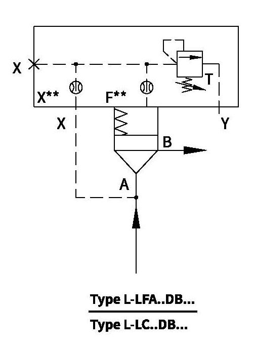
Function, section and symbol
Pressure reducing function
a) Normally open:
Control cover type L-LFA...DB...
Cartridge valve type L-LC..DR...
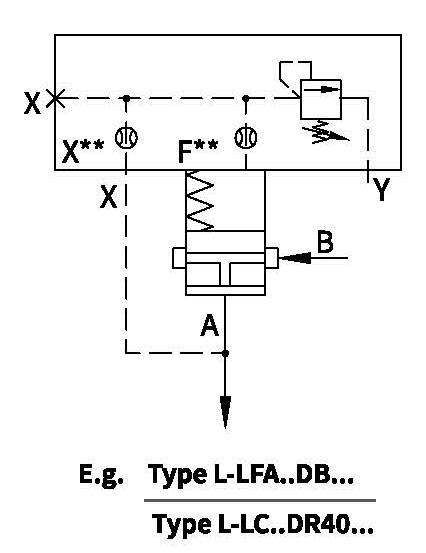
The cartridge valve for the pressure reducing function is a poppet valve with a area ratio of 1:1(no effective area at port B), adopting the same types of cover (type LFA ..DB...) used as pilot valves which are used for the pressure relief functions.
The pressure fed via the pilot oil orifice is acting on the main spring chamber. When pressure is below the setting of pilot valve, the forces on spool are balanced and the spool remains open due to the spring force. Consequently, fluid flows port B to port A free. On reaching the set pressure, spool closes and reduces the pressure at port A in line with the pressure-flow characteristics.
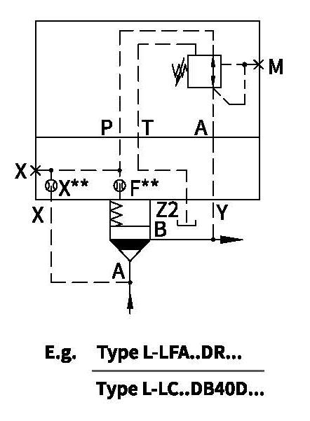
b) Normally closed:
Control cover type L-LFA...DR...
Cartridge valve type L-LC..DB...D...
For the pressure reducing function with opening characteristics, a pressure relief valve cartridge (type L-LC..DB..D...) and a control cover with a pressure reducing valve (type L-LFA..DR...) as the pilot valve are used. The pilot oil is fed from port A via the pilot orifice and the open pressure reducing valve to side B. The main spool opens and allows free flow from port A to port B. On reaching the setting pressure, the main spool closes and reduces the pressure at port B in line with the pressure-flow characteristics. If excess pressure occurs on the pressure reducing side, pressure relieves via the third port of the pilot valve. By fitting a directional valve, an additional isolating function can also be attained (type L-LFA..DRW...).
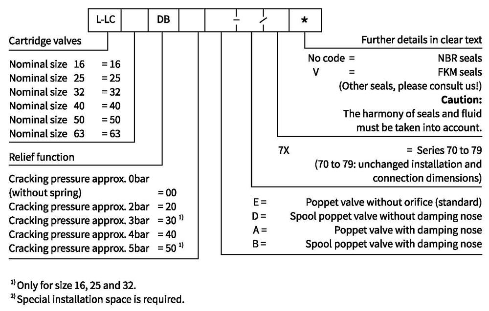
Ordering code
Pressure relief cartridge valve (without associated control cover)
Symbols
Cartridge valves (for versions see Ordering code)
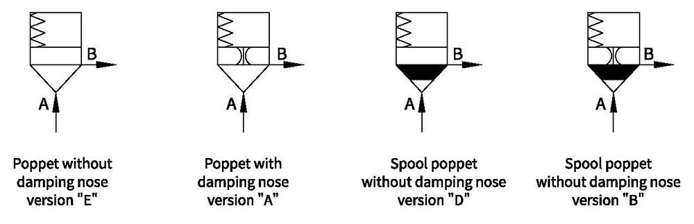
Technical data
| Fluid | Mineral oil suitable for NBR and FKM seal | ||||||
| Phosphate ester for FKM seal | |||||||
| Fluid temperature range ℃ | -30 to +80 (NBR seal) -20 to+80(FKM seal) | ||||||
| Viscosity range m㎡/s | 2.8 to 380 | ||||||
| Degree of contamination | Maximum permissible degree of fluid contamination: Class 9. NAS 1638 or 20/18/15, ISO4406 | ||||||
| 2-way cartridge valve | |||||||
| Max.operating pressure -Ports A and B bar | 420 | ||||||
| Max.flow-rate (recommendation) | Size | 16 | 25 | 32 | 40 | 50 | 63 |
| Poppet valve cartridge L/min "E"and"A" | 300 | 450 | 600 | 1000 | 1600 | 2500 | |
| Spool valve cartridge L/min "D"and"B" | 175 | 300 | 450 | 700 | 1400 | 1750 | |
1) To prevent the problem caused by fluid contamination, fluid cleanliness mentioned above must be met.
For applications outside these parameters, please consult us!
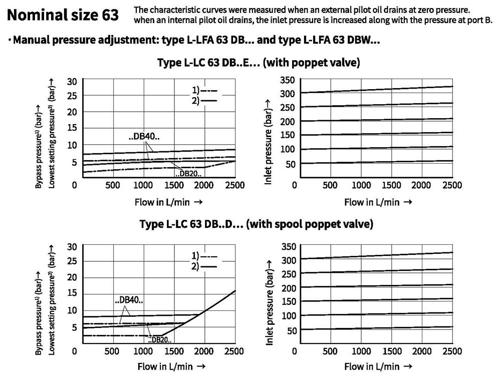
Characteristic curves (Measured at oil=40°C +5°C, using HLP46)
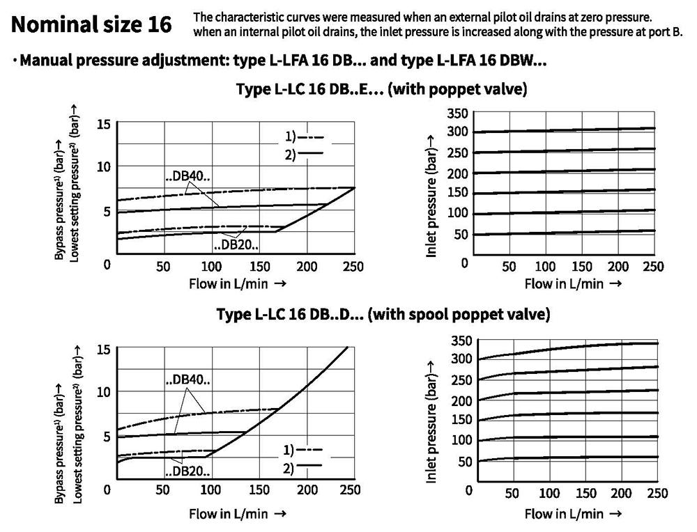
Characteristic curves (Measured at oil =40°C +5°C, using HLP46)
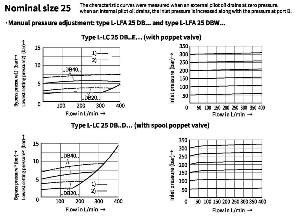
Characteristic curves (Measured at oil =40°C +5°C, using HLP46)
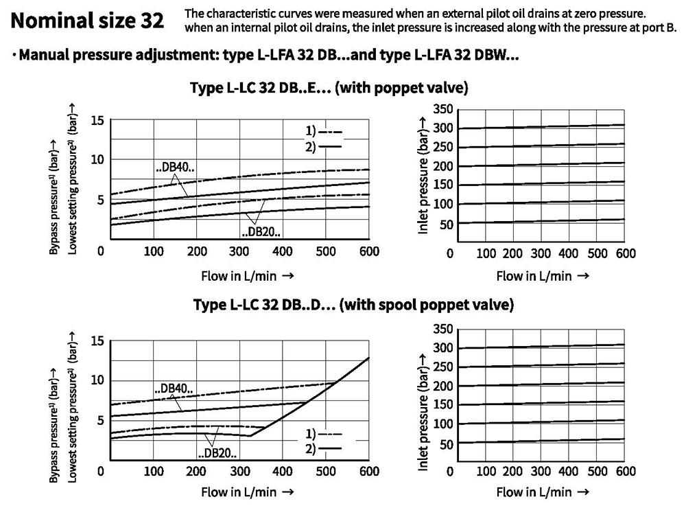
Characteristic curves(Measured at oil=40°C +5°C, using HLP46)
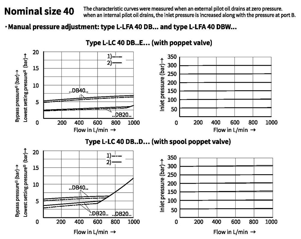
Characteristic curves (Measured at oil =40°C +5°C,using HLP46)
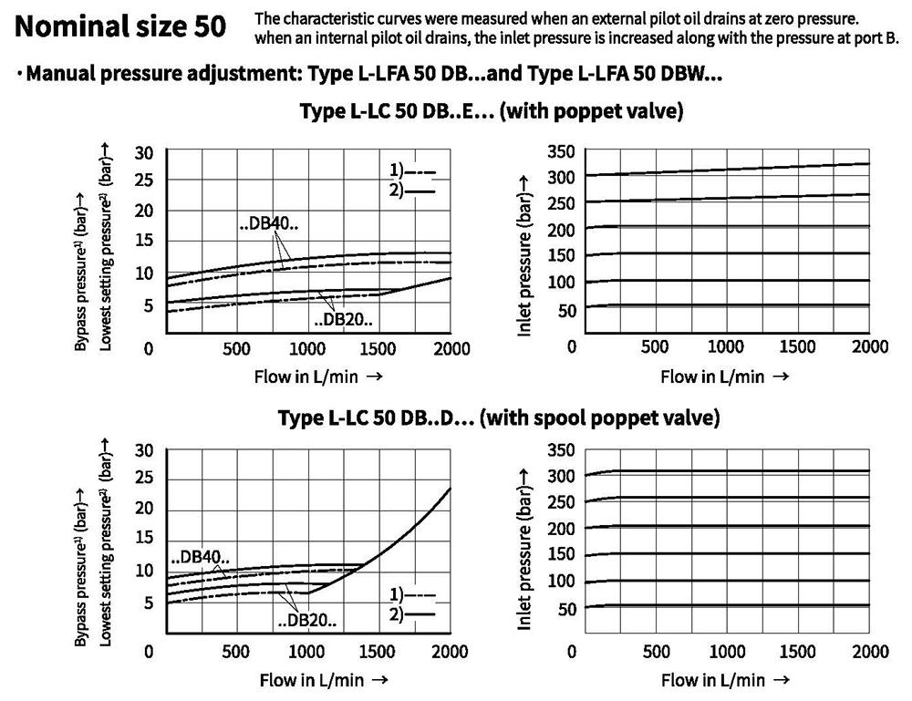
Characteristic curves (Measured at oil =40°C +5°C, using HLP46)
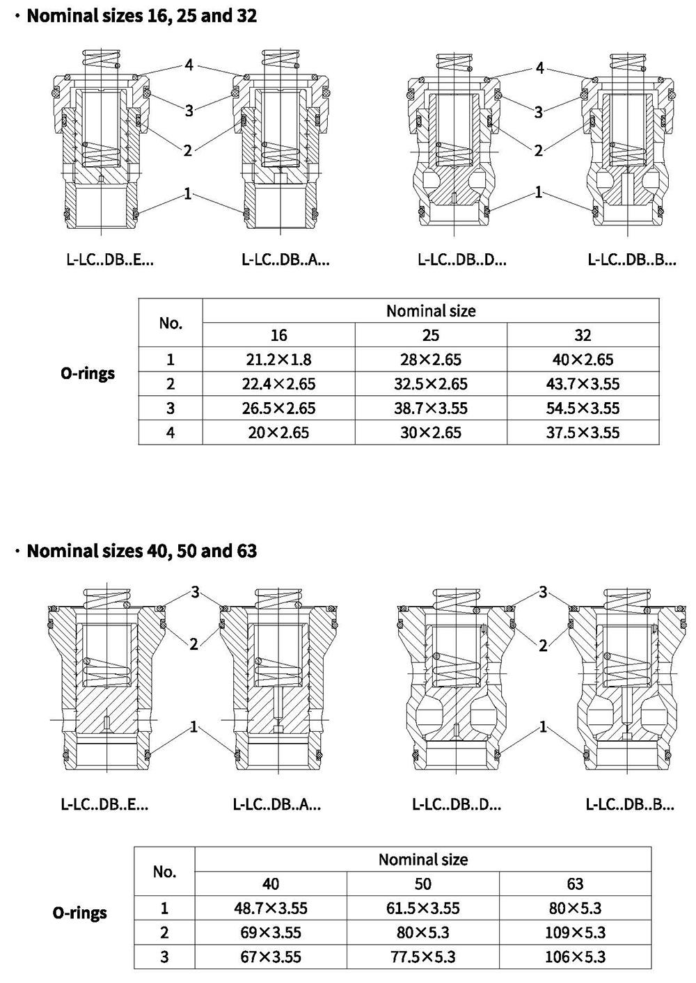
O-rings dimensions for type L-LC
Technical data (Max. operating pressure of pilot control valve)
| Control cover | Max. operating pressure Y,T bar | Remark | ||||
| Size | Type | X | pressure limitation | Static | ||
| DBD.2K-L20/... | 16 to 32 | DB,DBW,DBWD, DBU2.,DBBU3D, DBS | 420 | Zero pressure (about to 2 bar) | 315 | Supply included |
| DBD.6K10/...2) | 40 to 63 | 400 | 315 | |||
| .WE6... | 350 | 21(=);16(~) | Order seperately | |||
1) Possible pressure: 25,50,100,200,315,400
2) Possible pressure: 25,50, 100, 200, 315, 420
Technical data (Type L-LFA.DB..,for applications outside these parameters, please consult us!)
| Max.operating pressure bar | 420 Caution:the max. operating pressure Pmax of pilot valve should be taken into account. |
| Fluid | Mineral oil suitable for NBR and FKM seal |
| Phosphate ester for FKM seal | |
| Fluid temperature range ℃ | -30 to +80 (NBR seal) |
| -20 to+80(FKM seal) | |
| Viscosity range m㎡/s | 2.8 to 380 |
| Degree of contamination | Maximum permissible degree of fluid contamination: 3) Class 9. NAS 1638 or 20/18/15,ISO4406 |
3) To prevent the problem caused by fluid contamination, fluid cleanliness mentioned above must be met.
O-rings dimensions for ports X, Y (included within the scope of supply)
| Size | Dimension mm |
| 16 | 8x1.8 |
| 25 | 9.25x1.78 |
| 32 | 10.82x1.78 |
| Size | Dimension mm |
| 40 | 12x2.5 |
| 50 | |
| 63 | 18.72x2.62 |
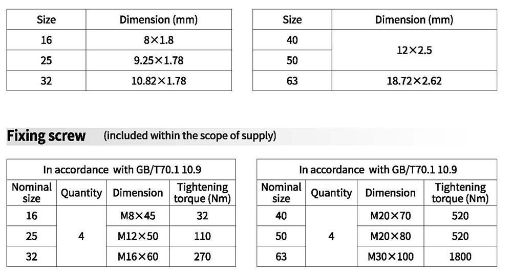
Mounting screw (included within the scope of supply)
| In accordance with GB/T70.1 10.9 | |||
| Nominal size | QTY | Dimension | Tightening toque (Nm) |
| 16 | 4 | M8x45 | 32 |
| 25 | M12x50 | 110 | |
| 32 | M16x60 | 270 | |
| 40 | M20x70 | 520 | |
| In accordance with GB/T70.1 10.9 | |||
| Nominal size | QTY | Dimension | Tightening toque (Nm) |
| 50 | 4 | M20x80 | 520 |
| 63 | M30x100 | 1800 | |
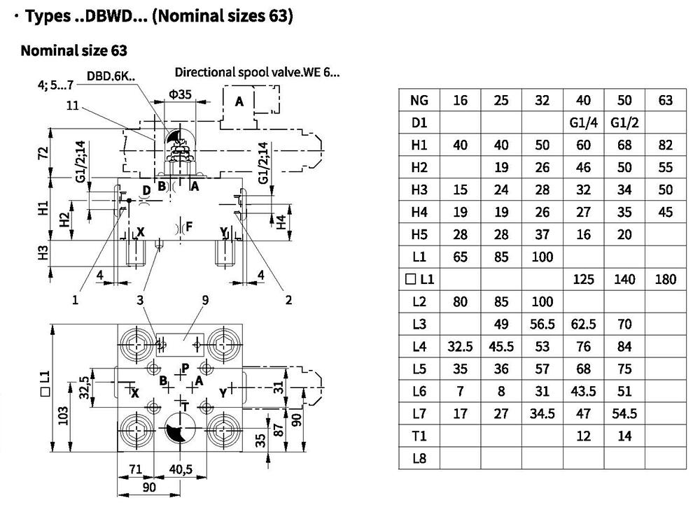
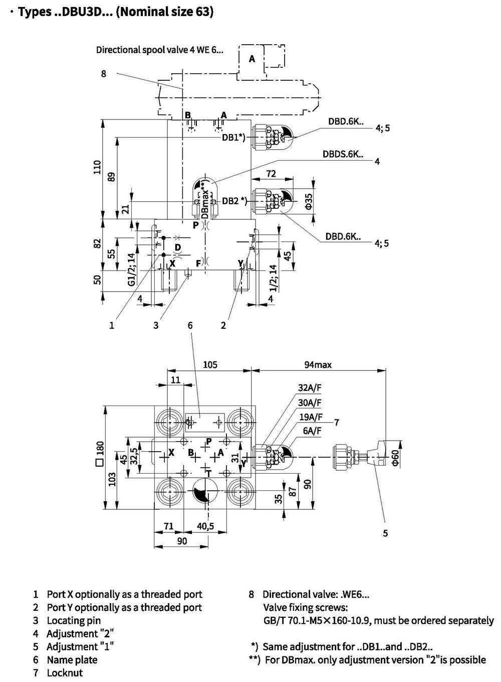
Control cover with manual pressure adjustment(Dimensions in mm)
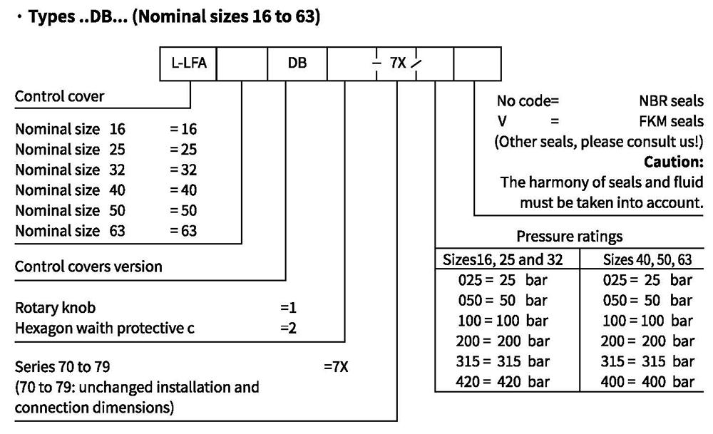
Control cover with manual pressure adjustment
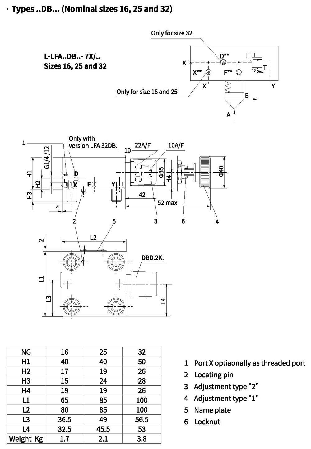
Control cover with manual pressure adjustment
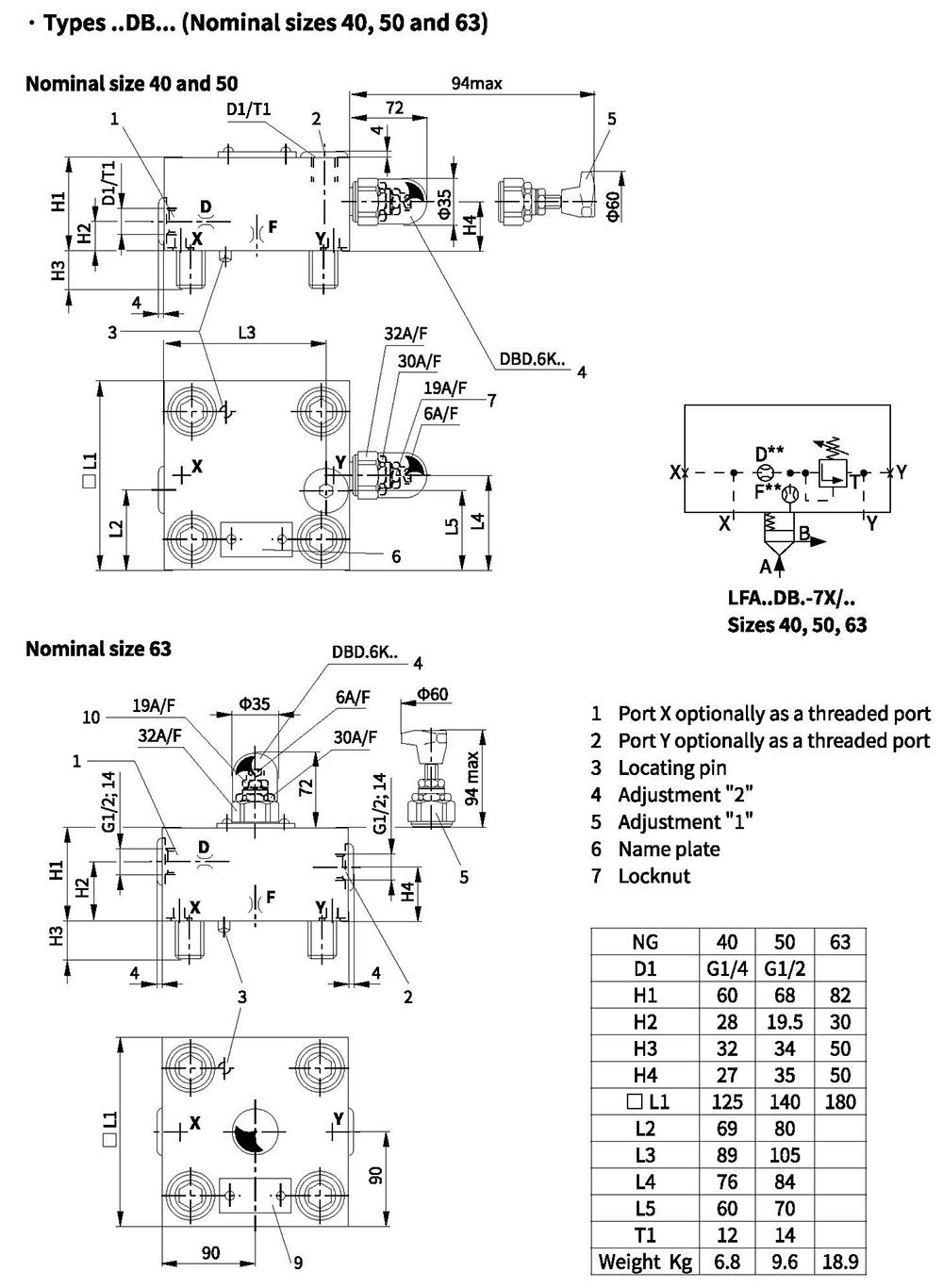
Control cover with manual pressure adjustment, with electrical unloading function
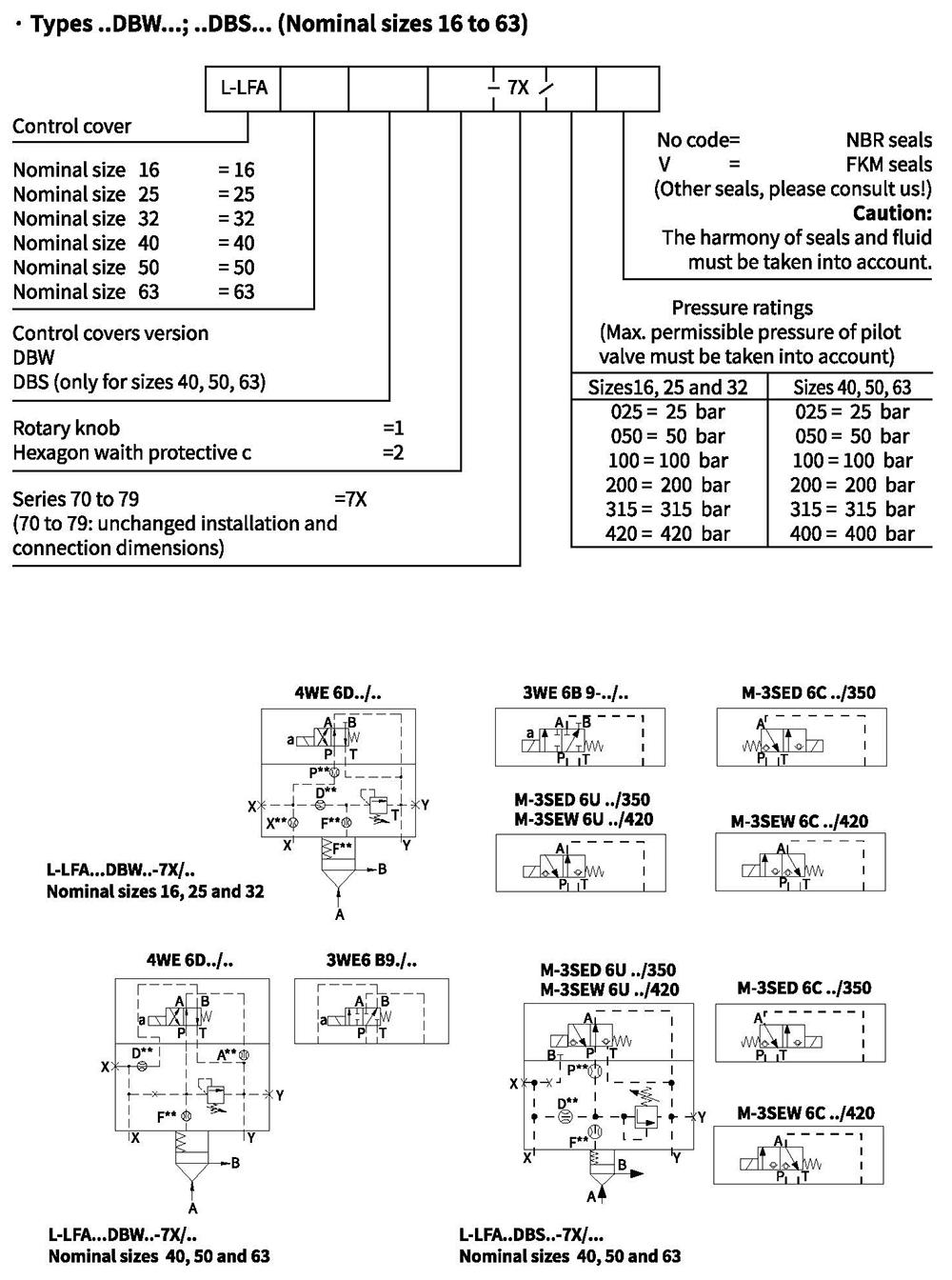
Control cover with manual pressure adjustment, with electrical unloading function
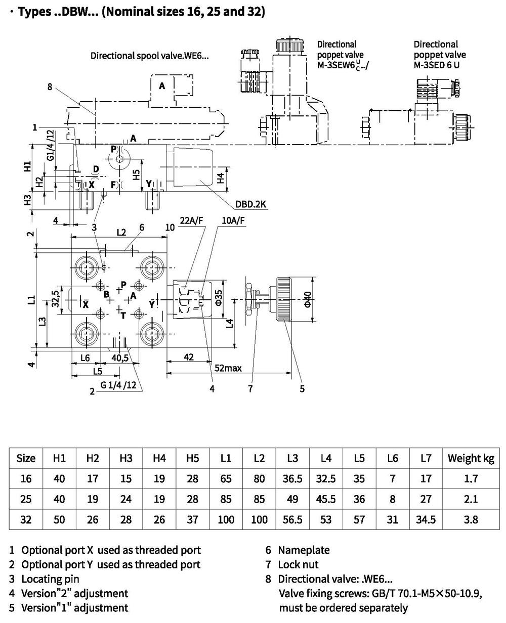
Control cover with manual pressure adjustment, with electrical unloading function
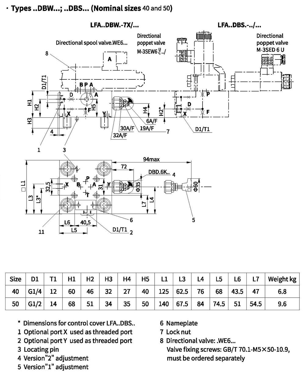
Control cover with manual pressure adjustment, with electrical unloading function
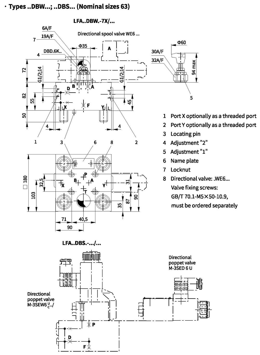
Control cover with manual pressure adjustment, with isolation function
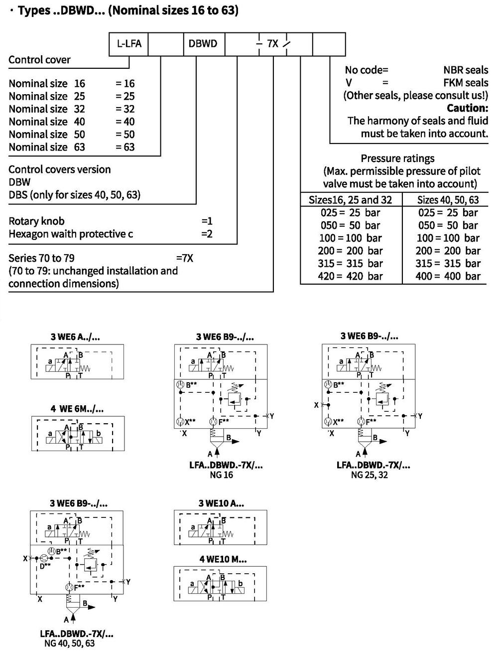
Control cover with manual pressure adjustment, with isolation function
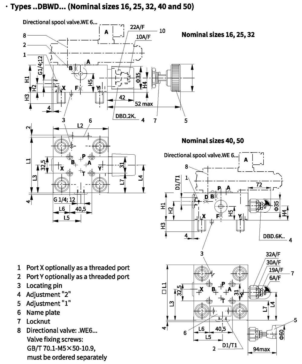
Control cover with manual pressure adjustment, with isolation function
Control cover with 2 manual pressure adjustments, selected electrically
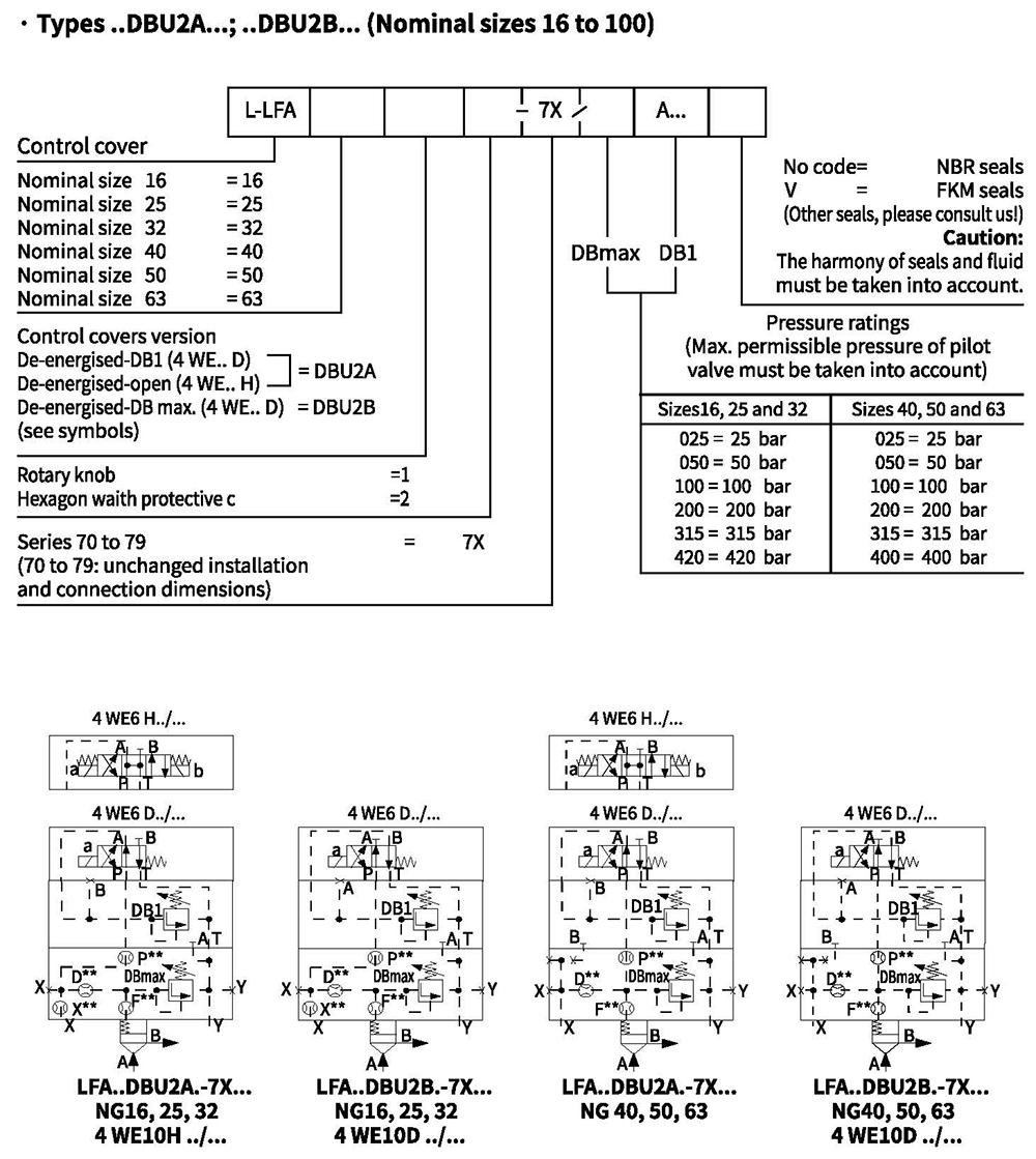
Control cover with 2 manual pressure adjustments, selected electrically
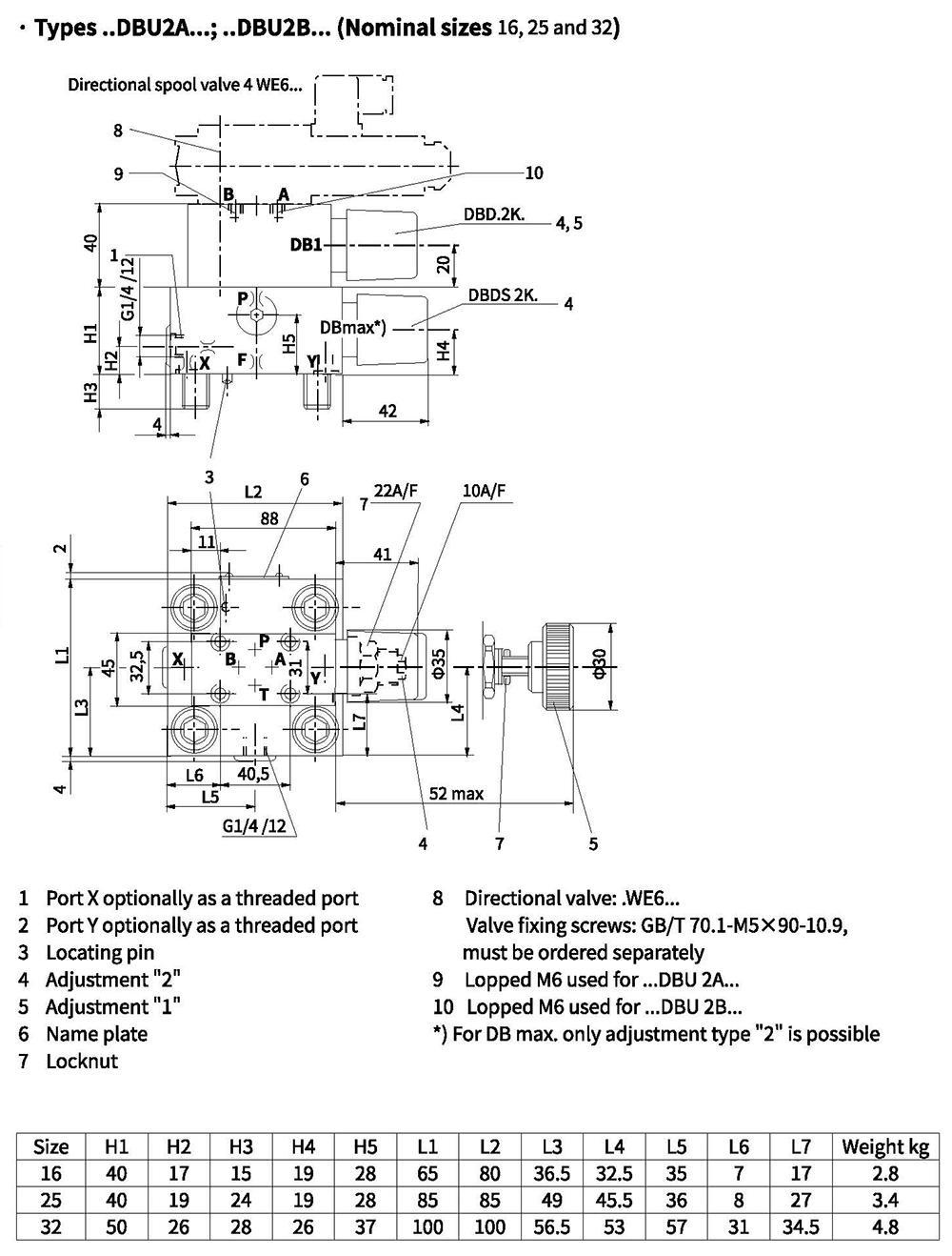
Control cover with manual pressure adjustment, selected electrically
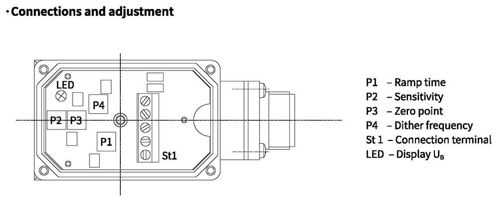
Control cover with 3 manual pressure adjustments, selected electrically
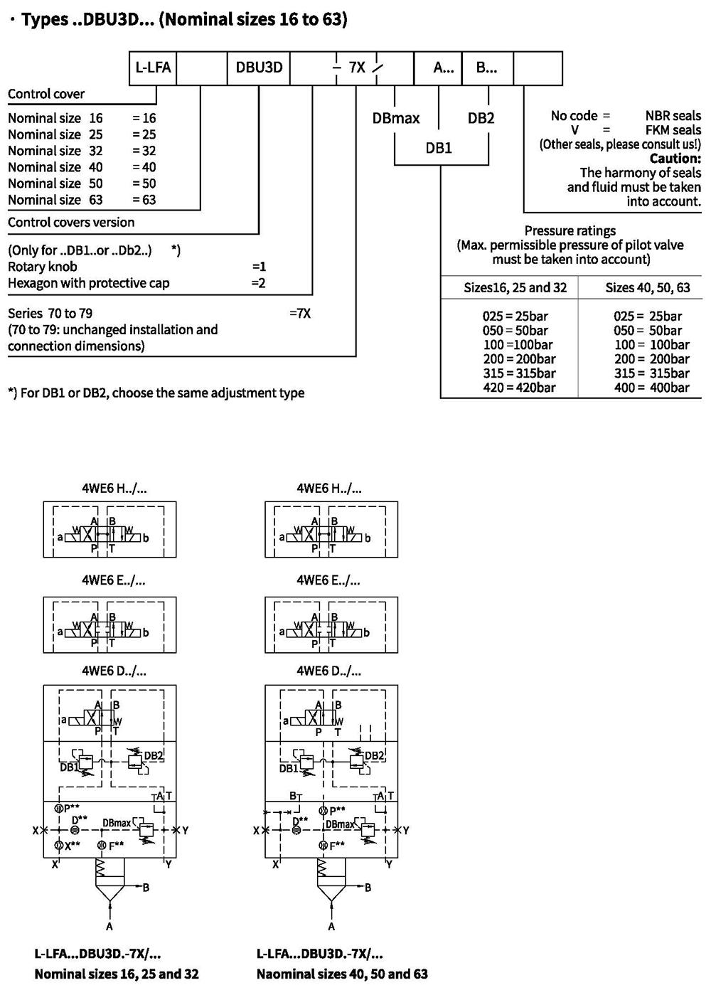
Control cover with 3 manual pressure adjustments, selected electrically
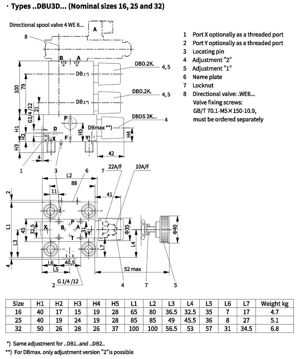
Control cover with 3 manual pressure adjustments, selected electrically
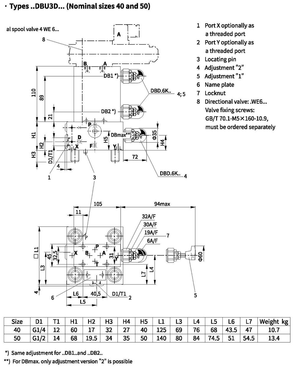
Control cover with 3 manual pressure adjustments, selected electrically
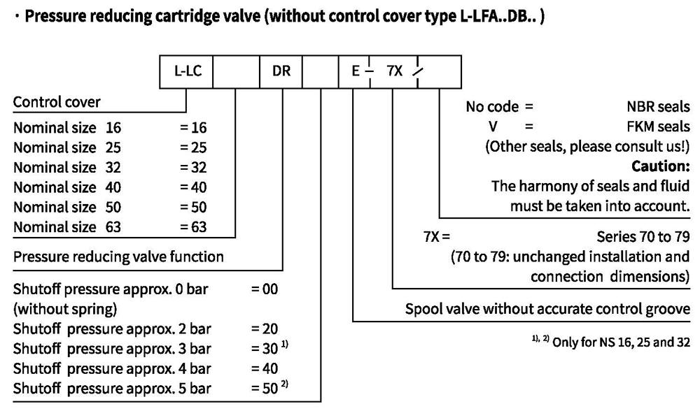
Ordering code
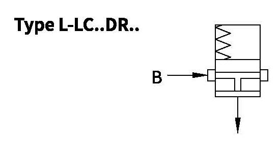
Symbol: Cartridge valve
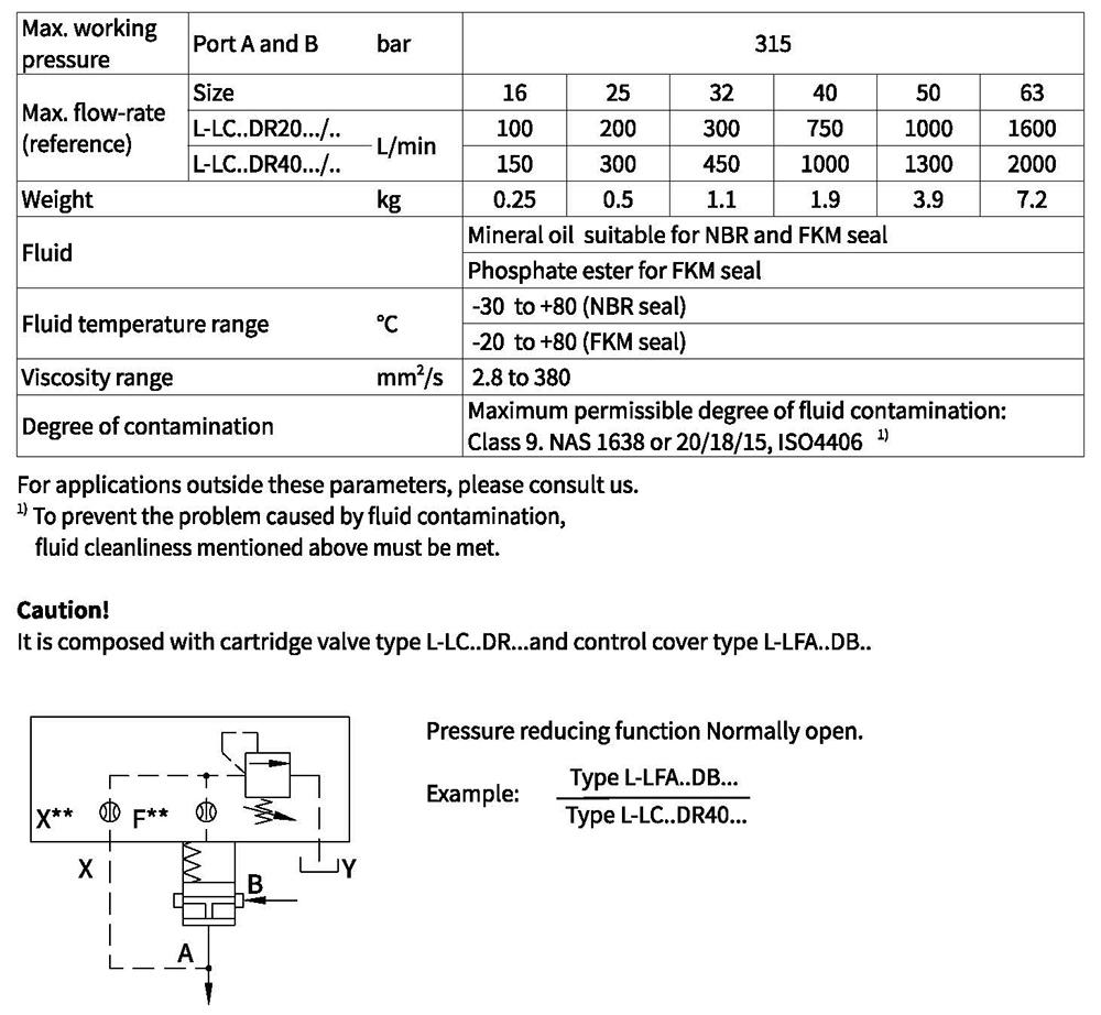
Technical data
Characteristic curves(Measured at oil =40°C +5°C, using HLP46)
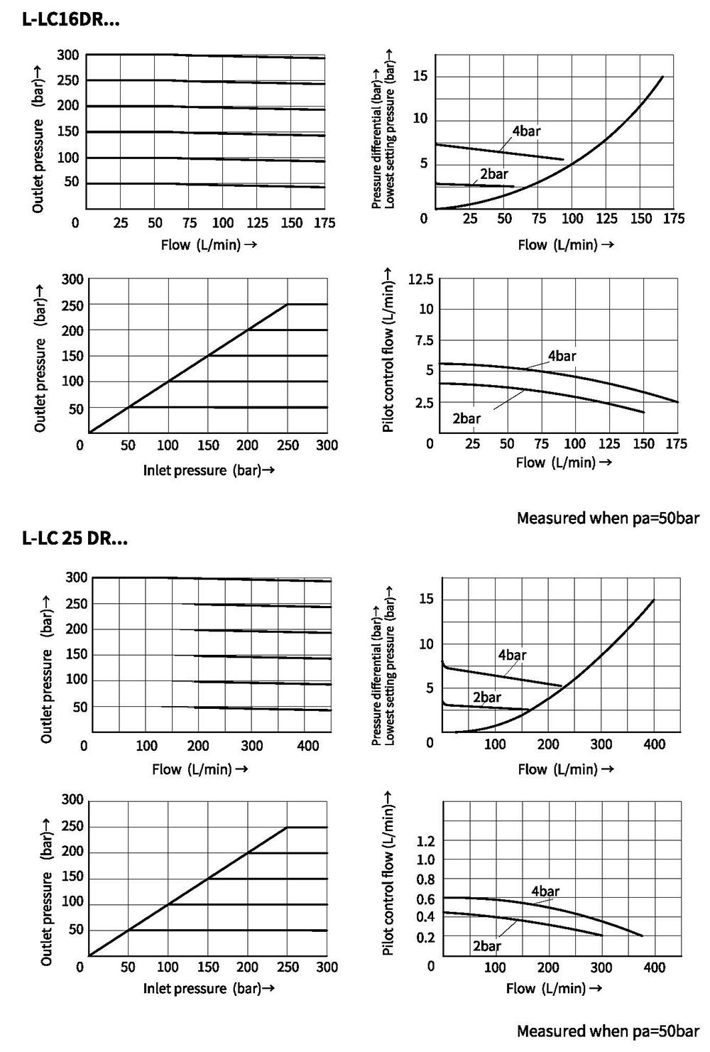 11
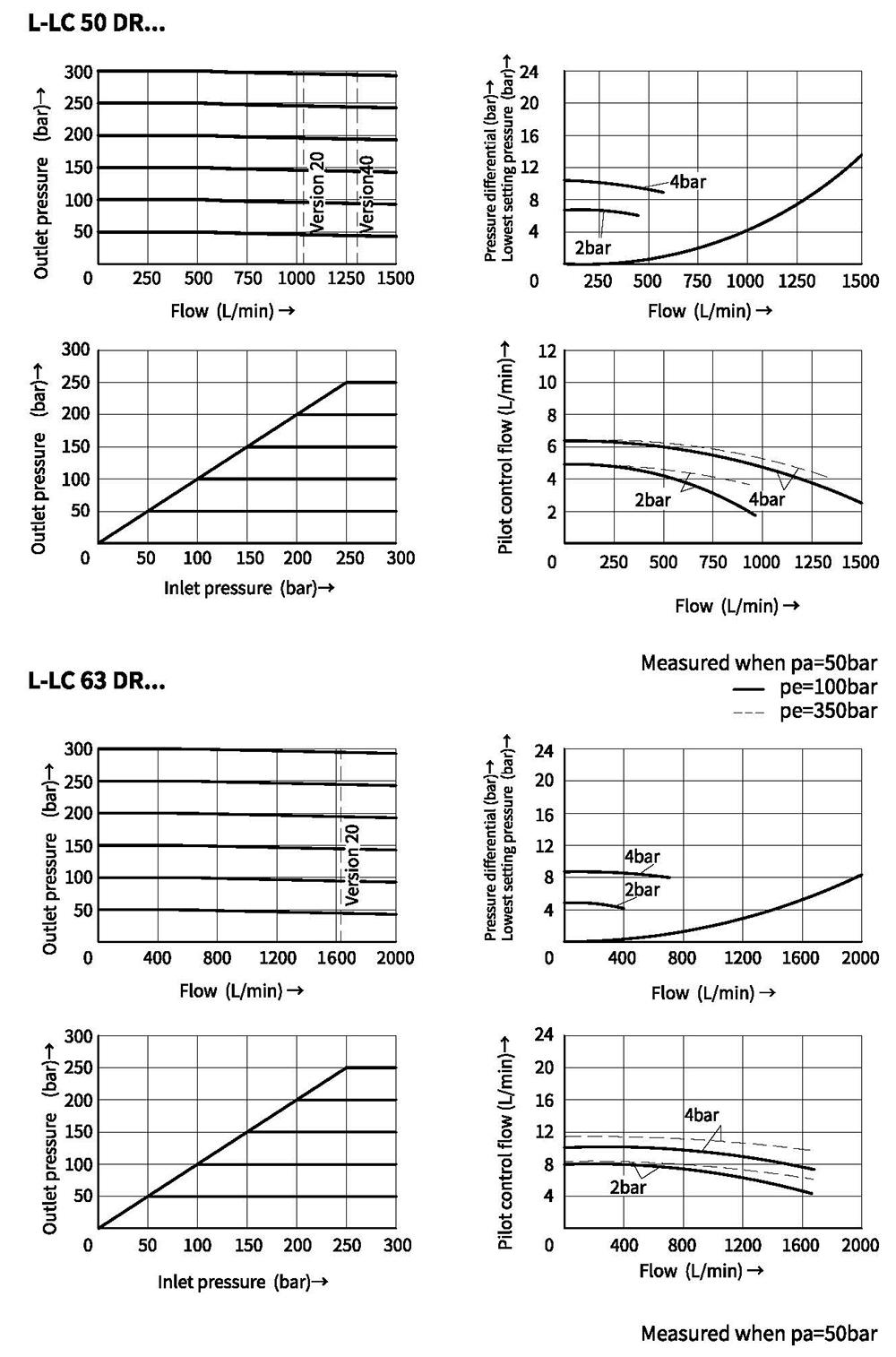
Characteristic curves(Measured at oil=40°C +5°C, using HLP46)
Characteristic curves(Measured at oil=40°C +5°C, using HLP46)
O-rings for cartridge valve type L-LC
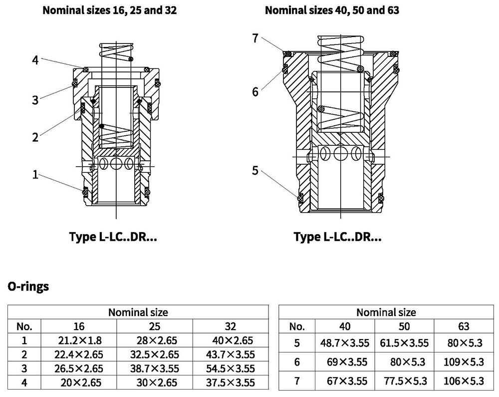
Technical data
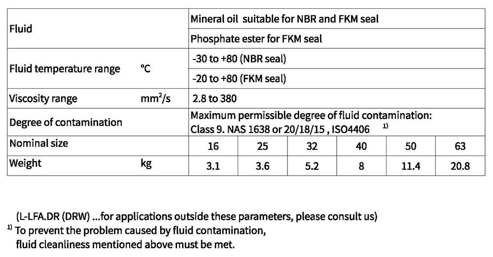
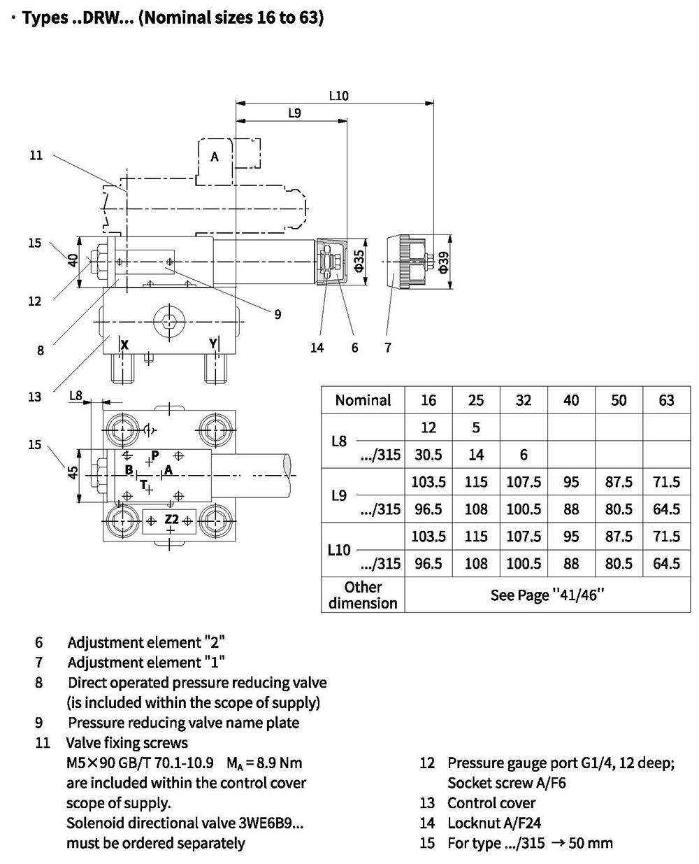
Control cover with pressure reducing function
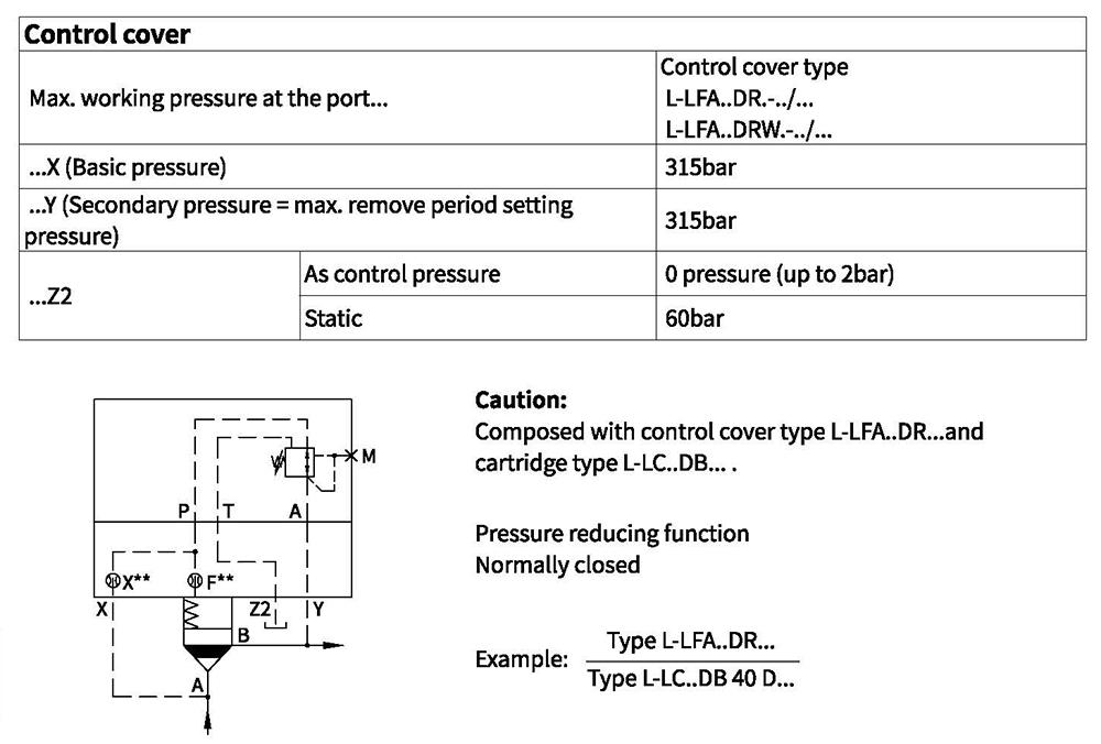
O-rings dimensions for ports X, Y, Z1, Z2
 11
Control cover with pressure reducing function
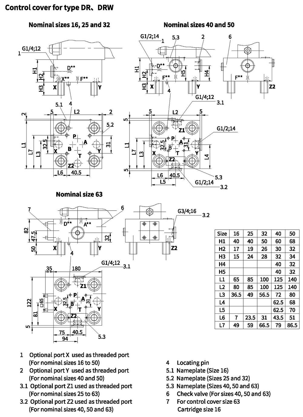
Control cover with pressure reducing function
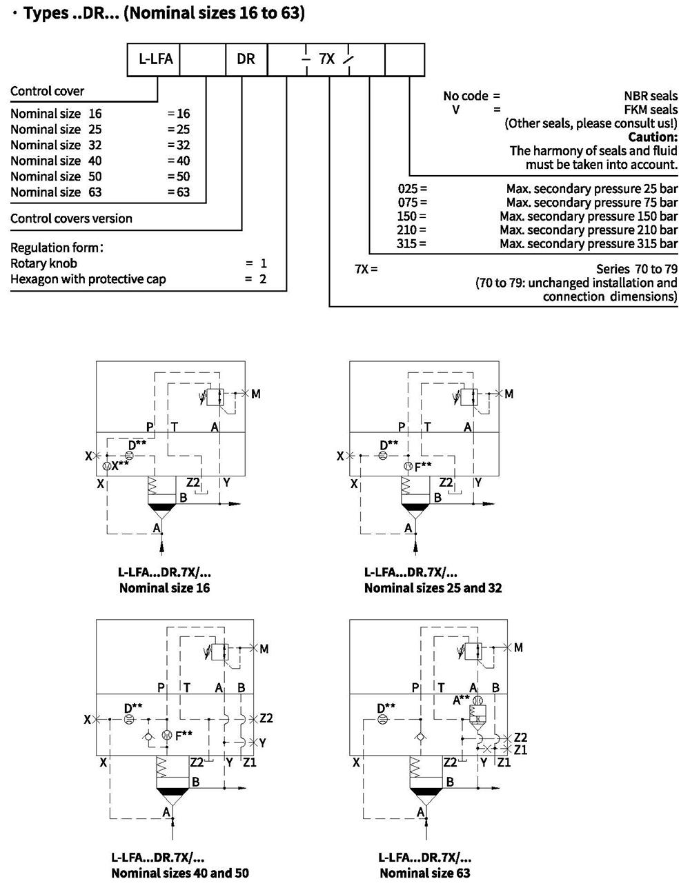
Control cover with pressure reducing function
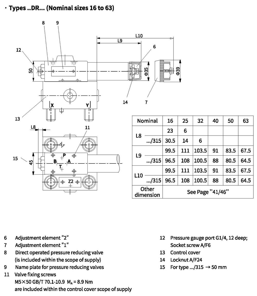
Control cover with pressure reducing function
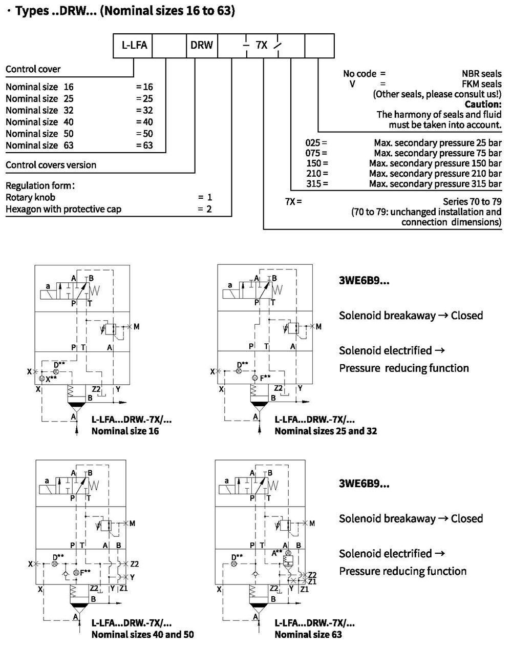
Control cover with pressure reducing function