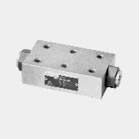
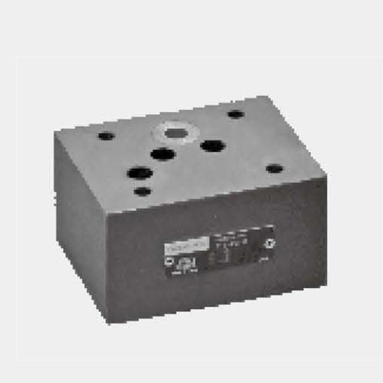
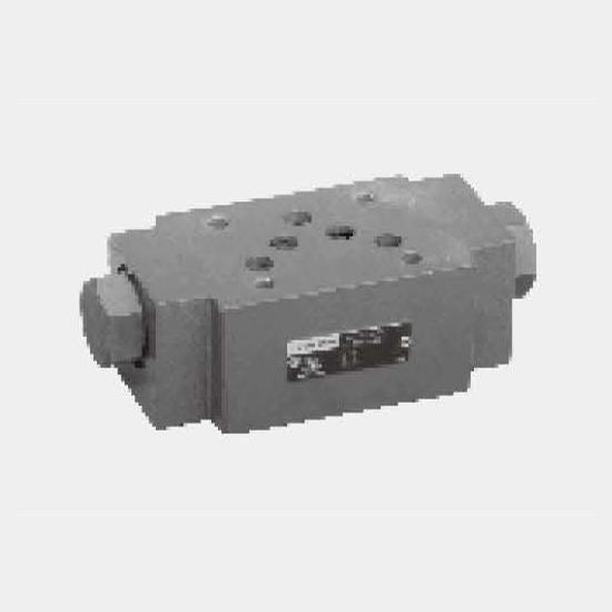
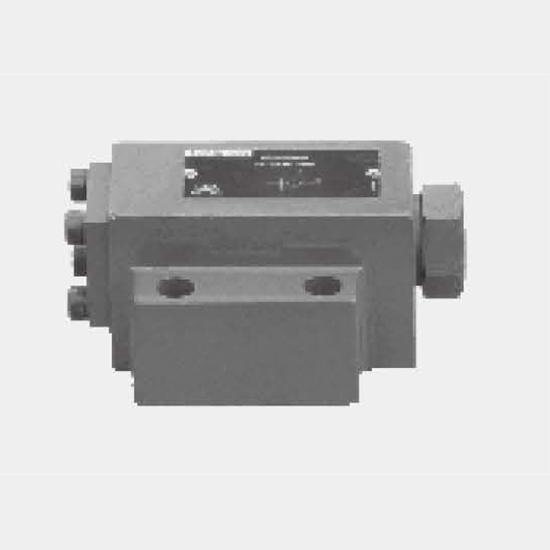
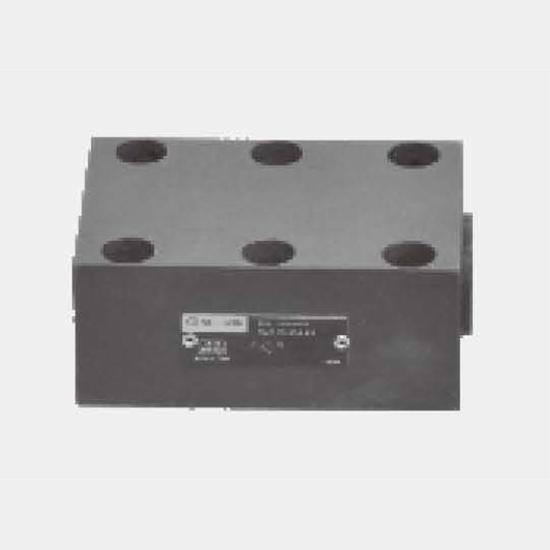
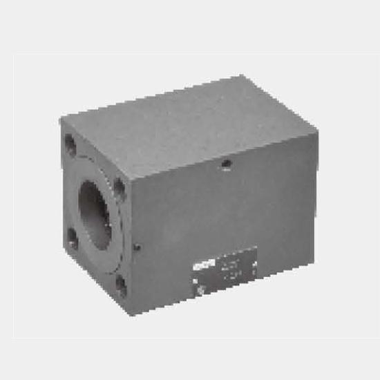
Function and configurationsValves of types SV and SL are pilot operated check valves of poppet design that can be opened in the checked direction. These valves are used to isolate pressurised working ...
Product Detail
Function and configurations
Valves of types SV and SL are pilot operated check valves of poppet design that can be opened in the checked direction. These valves are used to isolate pressurised working circuits, to prevent a load from lowering in the event of a pipe rupture or to protect hydraulically isolated actuators from creeping down.
They basically consist of the housing(1),the poppet (2), a compression spring (3) and the pilot piston (4).
Type SV... (without drain port) Fluid may flow freely from A to B. In the reverse direction, the poppet (2) is held firmly on to its seat both by the compression spring and the system pressure.
By applying pressure to pilot connection X, the pilot piston (4) is moved to the right. This lifts poppet (2)
off its seat, then fluid flows from B to A.
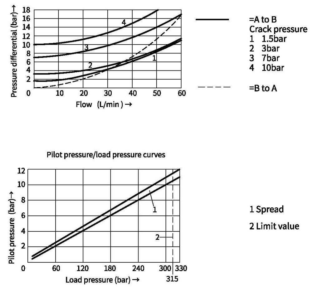
In order to ensure that the valve opens due to pressure applied to the pilot piston,a certain minimum pilot pressure is required (see next page).
The drain port Y is plugged.
Type SL...(with drain port)
In principle, the function of this valve corresponds to that of type SV.
The difference lies in the additional drain port Y for type SL, the annular area of the pilot piston (4) is
separated from the port A. Pressure present in port A acts only on area A3 (7) of the pilot.
It is used in the situation having load on port A when valve opens, while type SV is used in that unloading on port A when this valve opens.
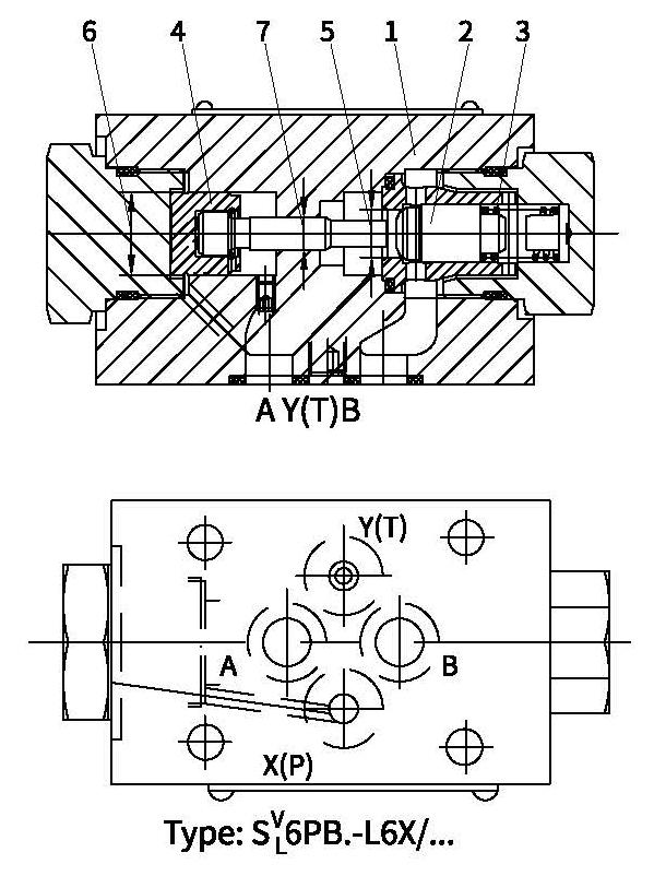
1 Housing
2 Poppet
3 Compression spring
4 Pilot piston
5 Area A1
6 Area A2
7 Area A3
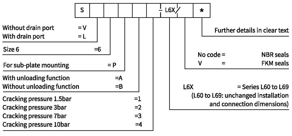
Symbols
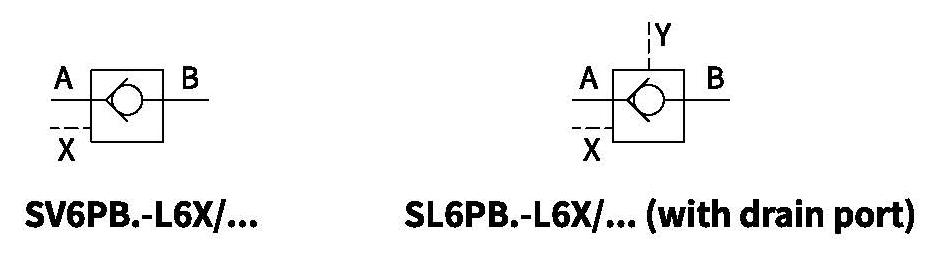
Ordering code
Technical data
| Weight kg | Approx.0.8 |
| Installation position | Optional |
| Flow direction | A to B flow freely, B to A flow under pilot |
| Operating pressure bar | To 315 |
| Pilot pressure bar | 5 to 315 |
| Control flow-Port X cm3 | 0.68 |
| -Port Y(only type SL) cm3 | 0.58 |
| Control area-area A1 c㎡ | 0.42 |
| -area A2 c㎡ | 1.33 |
| -area A3 c㎡ | 0.19 |
| Viscosity range m㎡/s | 2.8 to 500 |
| Fluid temperature range ℃ | -30 to +80 (NBR seal) |
| -20 to+80 (FKM seal) | |
| Fluid | Mineral oil suit for NBR and FKM seal |
| Phosphate ester for FKM seal | |
| Degree of contamination | Maximum permissible degree of fluid contamination: Class 9. NAS 1638 or 20/18/15, ISO4406 |
Characteristic curves (Measured at 9oil=40℃ ±5℃ ,using HLP46)
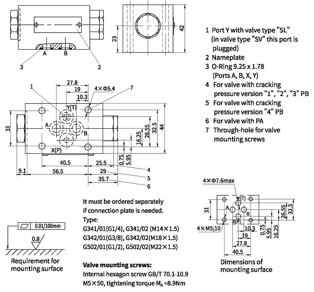
Unit dimensions