Function and configurationThe check valve type S permits free flow in onedirection and closure in opposite direction withleakage.It basically comprises of the housing (1), poppet(2) compression spring...
Product Detail
Function and configuration
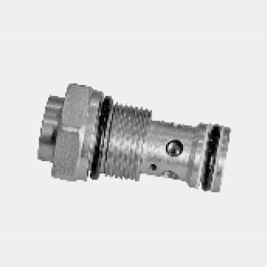
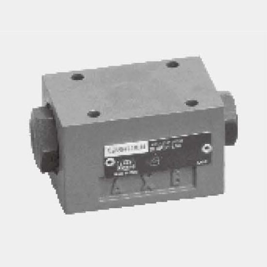
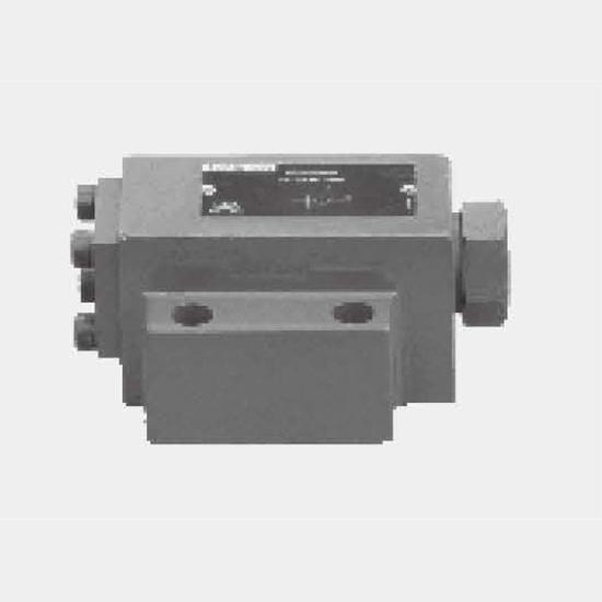
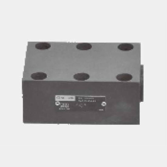
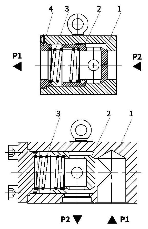
The check valve type S permits free flow in onedirection and closure in opposite direction withleakage.It basically comprises of the housing (1), poppet(2) compression spring (3) and the spring seat(4).The stroke of the poppet (2), which is guided onits outside diameter, is limited by a mechanicalstop---the spring seat(4). The built-in compressionspring (3) supports the closing movement. Thecompression spring(3) holds the poppet (2) in theclosed position even when there is no flow throughthe valve.
When fluid flows through the valve in the opendirection, the poppet (2) lifts due to the fluidpressure. In the opposite direction the compressionspring (3) and the fluid presses the poppet (2) ontoits seat (4) and thus closes the connection.For check valves without spring, the fixed positionshould ensure that the poppet can locate itselfclosed under its gravity.
Ordering code
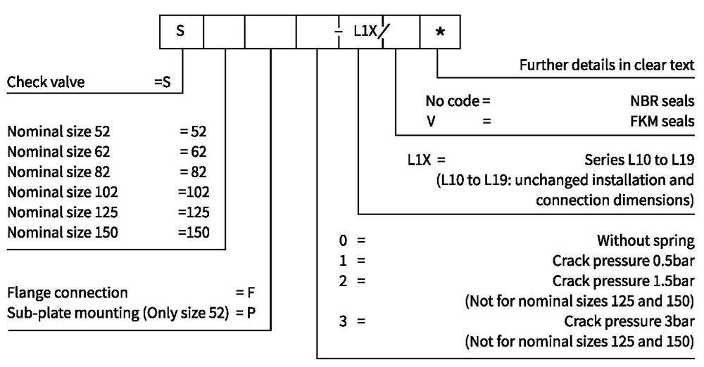
Technical data
| Max. operating pressure bar | 315 | |||||
| Crack pressure bar | Refer to the characteristic curve | |||||
| Max.flow-rate L/min | Refer to the characteristic curve | |||||
| Viscosity range m㎡/s | 2.8 to 500 | |||||
| Fluid temperature range ℃ | -30 to +80 (NBR seal) | |||||
| -20 to+80 (FKM seal) | ||||||
| Fluid | Mineral oil suit for NBR and FKM seal | |||||
| Phosphate ester for FKM seal | ||||||
| Degree of contamination | Maximum permissible degree of fluid contamination: Class 9. NAS 1638 or 20/18/15, ISO4406 | |||||
| Size | 52 | 62 | 82 | 102 | 125 | 150 |
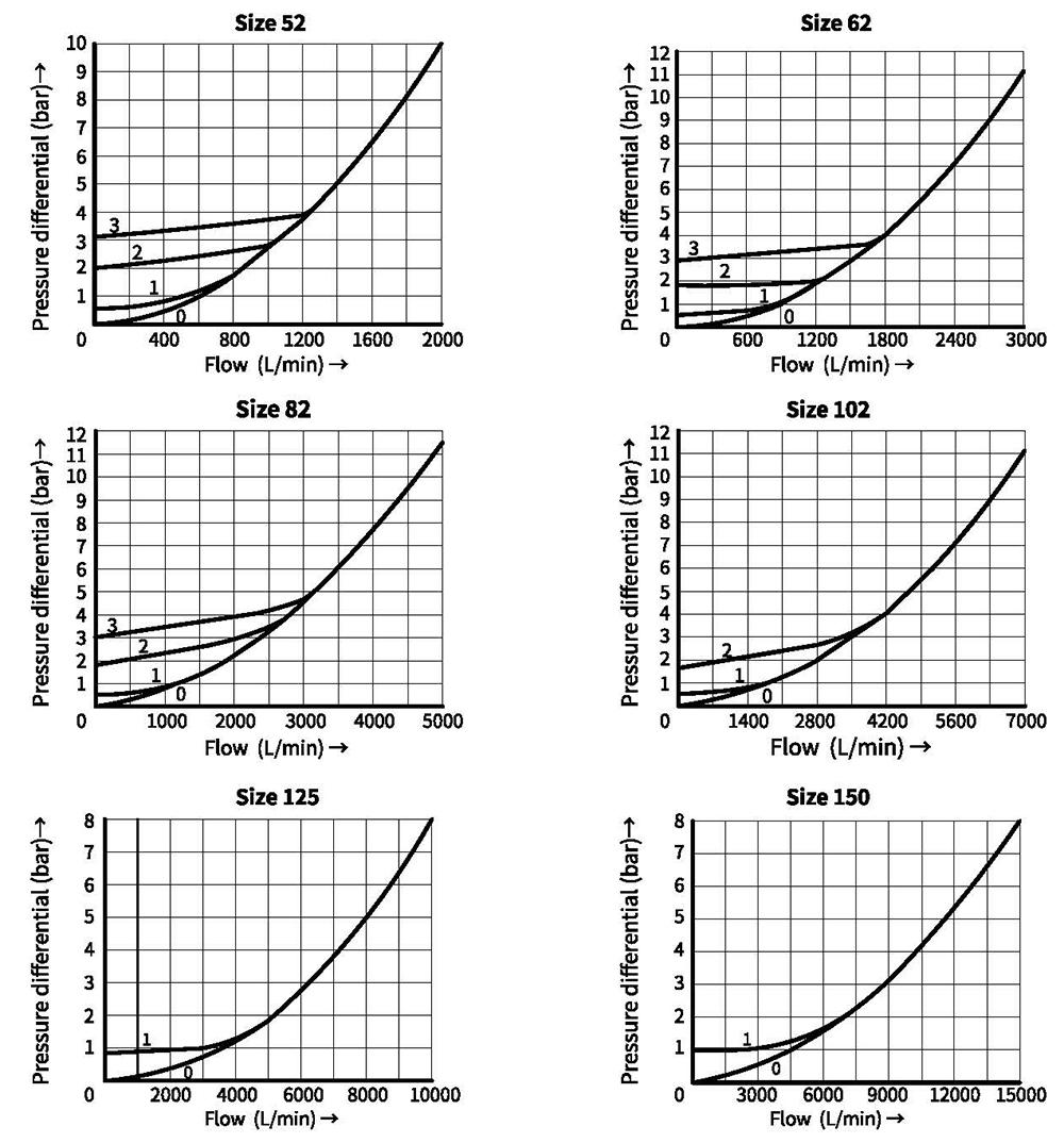
Characteristic curves(Measured at 8o =40°C +5°C, using HLP46)
Pressure differential AP in relation to the flow Q at the cracking pressure.
Unit dimensions: sub-plate mounting
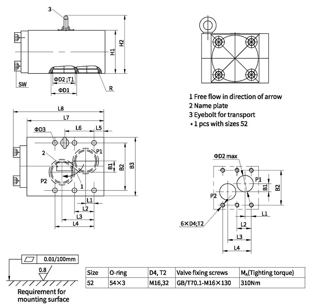
| Size | B1 | B2 | B3 | ΦD1 | ΦD2 | ΦD3 | H1 | H2 | L1 | L2 | L3 | L4 | L5 | L6 | L7 | L8 | T1 | A/F | Weight (kg) |
| 52 | 40 | 115 | 145 | 60 | 50 | 18 | 105 | 141 | 25 | 50 | 77 | 100 | 12 | 75 | 172 | 207 | 2.3 | 14 | 20 |
Unit dimensions: flange connection sizes 52 to 102
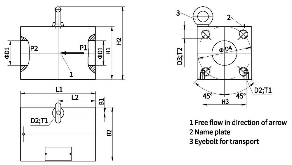
| Size | B1 | B2 | ΦD1 | D2 | D3 | ΦD4 | H1 | H2 | L1 | L2 | T1 | T2 | H3 | Weight(kg) |
| 52 | 10 | 100 | 45 | M10 | M16 | 98 | 98 | 134 | 135.5 | 67.5 | 15 | 26 | 80 | 10 |
| 62 | 10 | 120 | 55 | M10 | M20 | 118 | 118 | 154 | 165.5 | 82.5 | 15 | 32 | 100 | 15 |
| 82 | 15 | 150 | 72 | M12 | M24 | 145 | 148 | 184 | 195.5 | 97.5 | 20 | 36 | 120 | 34 |
| 102 | 15 | 180 | 90 | M12 | M30 | 175 | 178 | 214 | 245.5 | 122.5 | 20 | 40 | 150 | 62 |
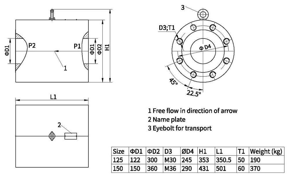
Unit dimensions: flange connection sizes 125 to 150