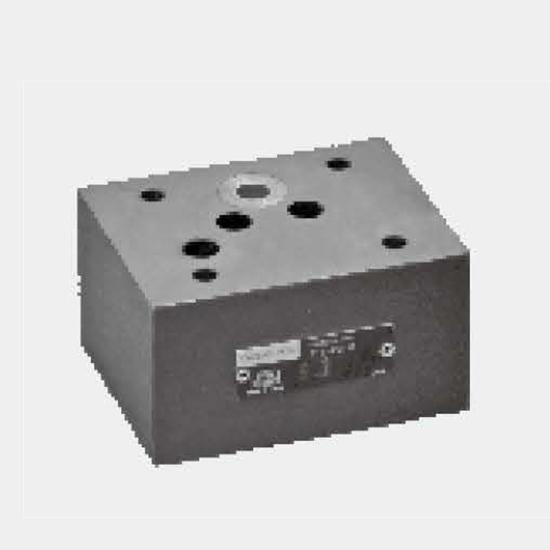
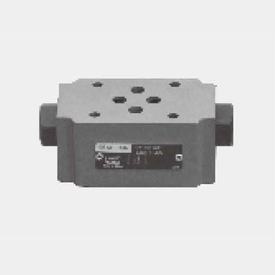
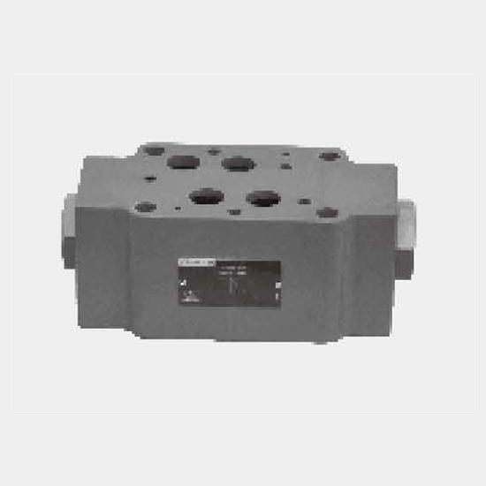
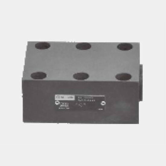
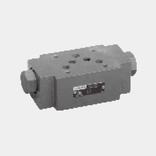
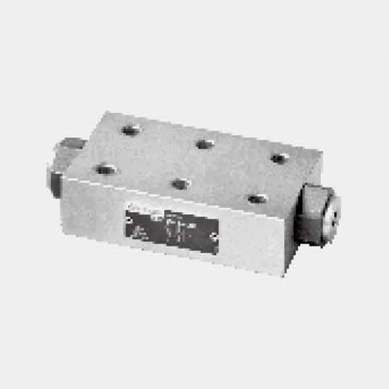
Function and configurationSV and SL valves are hydraulic pilot operated check valves in poppet type design which may be opened to permit reverse flow.These valves are used for the isolation of operati...
Product Detail
Function and configuration
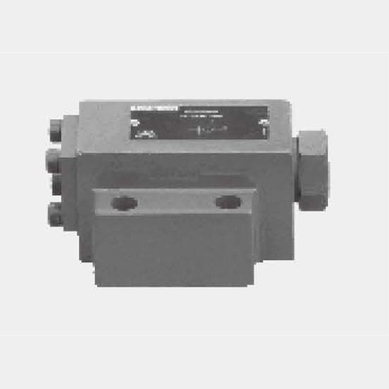
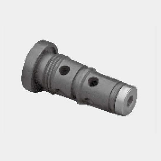
SV and SL valves are hydraulic pilot operated check valves in poppet type design which may be opened to permit reverse flow.
These valves are used for the isolation of operating circuits under pressure, to prevent a load from falling or creeping movements of hydraulically locked-in actuators.
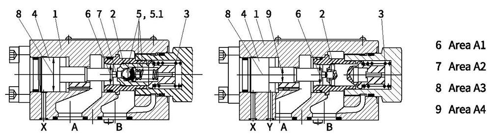
Basically these valves consist of housing (1), poppet (2), compression spring (3), control spool (4) as well as a optional pre-opening ball poppet valve (5).
Type SV (without drain port)
The valve permits free-flow from A to B. In the reverse direction, the poppet (2) is held firmly on to its seat in addition to the spring force by the system pressure.
By applying pressure at control port X the control piston (4) is moved to the right. This lifts the poppet (2) from the seat, then fluid flows from B to A.
In order to ensure the valve opens due to the pressure applied to the control piston (4) a certain minimum pilot pressure is necessary.
Type SV...A...and SL...A... (with pre-opening)
This valve has a additional decompression feature. When pressure is applied at control port X the control piston (4) is pushed to the right. The ball poppet(5.1) leaves first then the poppet (2) leaves from the seat. Now the valve may also have a flow from B to A.
Because of the pre-opening there is a dampened decompression of the fluid under pressure to avoid possible pressure shocks.
Type SL... (with drain port )
The function of this valve corresponds to the valve SV.
The difference is the additional leakage port Y. The annular area of the control piston (4) is separated from port A. The pressure at port A only effects area A4 (9) of the control piston (4).
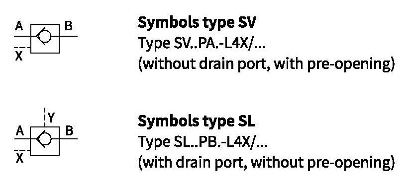
Symbols
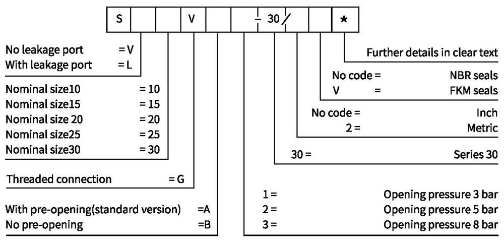
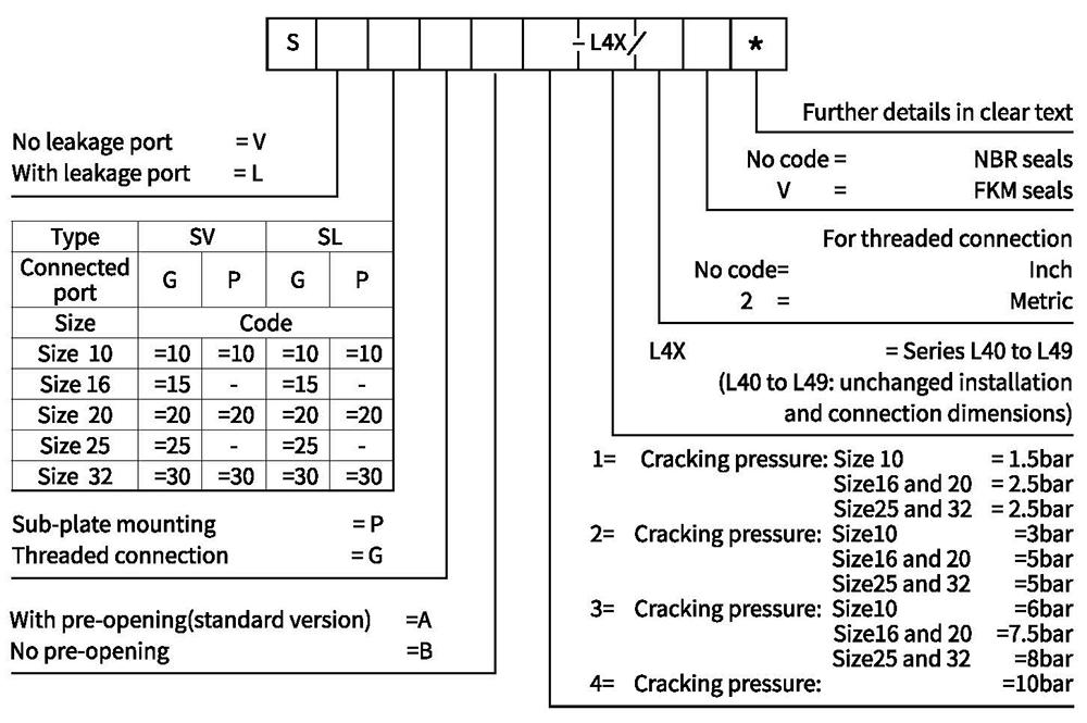
Ordering code
Technical data
| Nominal size | 10 | 16 | 20 | 25 | 32 | ||
| Weight | Sub plate mounting | kg | 2.1 | 4.7 | 7.8 | ||
| Threaded connection | kg | 2.5 | 5.7 | 5.7 | 10 | 10 | |
| Installation position | Optional | ||||||
| Flow direction | From A to B free, from B to A through opening | ||||||
| Operating pressrure | bar | To 315 | |||||
| Port pilot pressure | bar | 5 to 315 | |||||
| Control capacity-Port X | cm | 2.5 | 10.8 | 10.8 | 19.27 | 19.27 | |
| -Port Y(only type SL) | cm3 | 2 | 9.6 | 9.6 | 17.5 | 17.5 | |
| Control area-area A1 | c㎡ | 1.33 | 3.46 | 3.46 | 5.72 | 5.72 | |
| -area A2 | c㎡ | 0.33 | 0.7 | 0.7 | 1.33 | 1.33 | |
| -area A3 | c㎡ | 3.8 | 10.17 | 10.17 | 16.61 | 16.61 | |
| -area A4 | c㎡ | 0.79 | 1.13 | 1.13 | 1.54 | 1.54 | |
| Viscosity range | m㎡/s | 10 to 800 | |||||
| Fluid temperature range | ℃ | -30 to +80 (NBR seal) | |||||
| -20 to+80(FKM seal) | |||||||
| Fluid | Mineral oil suitable for NBR and FKM seal | ||||||
| Phosphate ester for FKM seal | |||||||
| Degree of contamination | Maximum permissible degree of fluid contamination: Class 9. NAS 1638 or 20/18/15,ISO4406 | ||||||
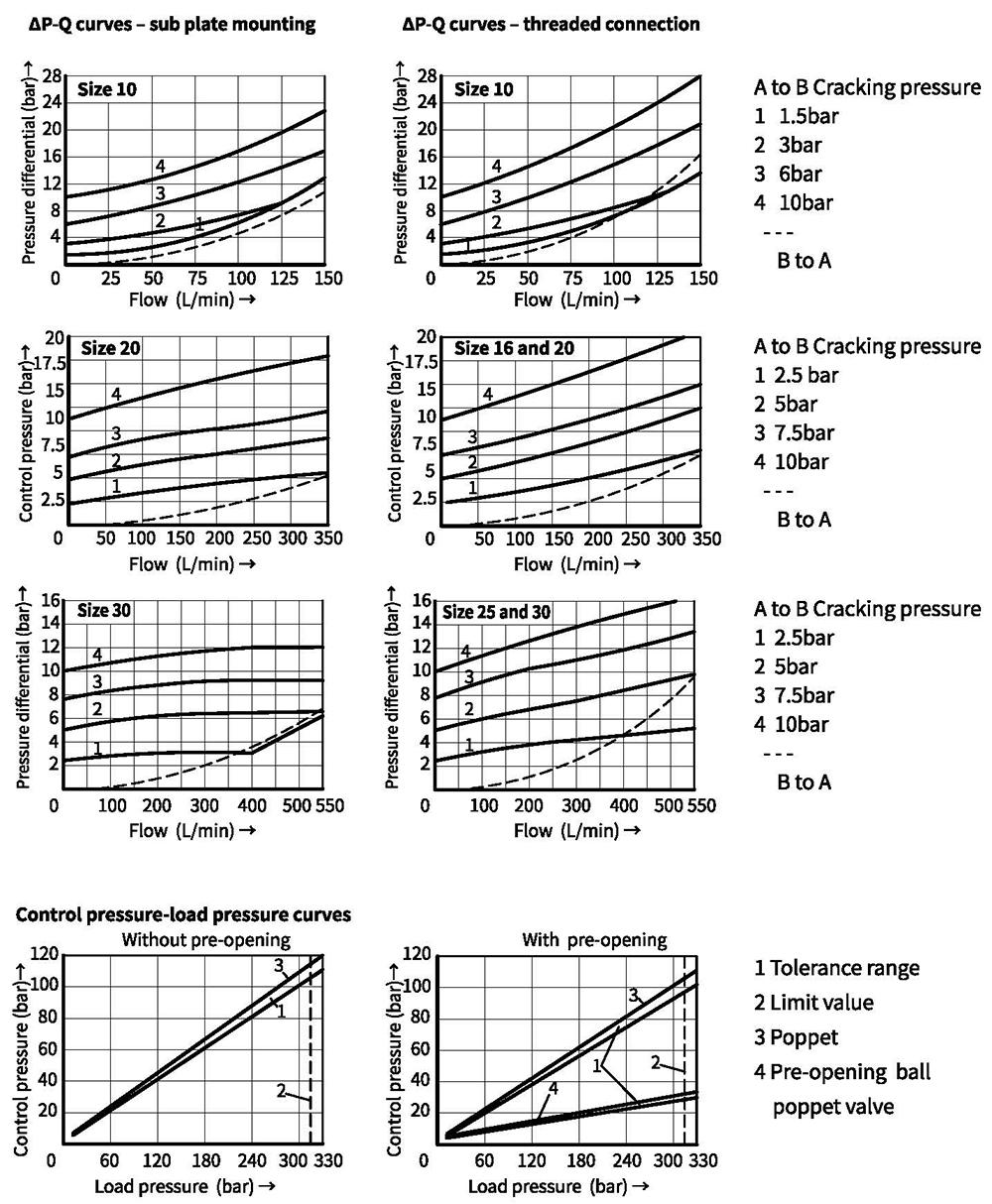
Characteristic curves (Measured at θₒᵢₗ=40℃ ±5℃, unless otherwise)
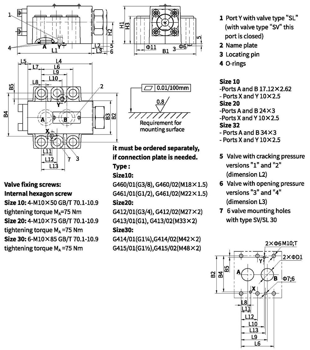
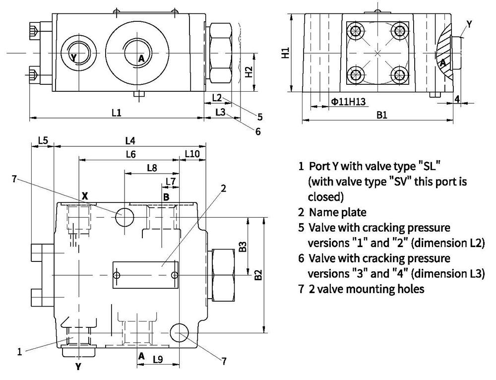
Unit dimensions
·sub-plate mounting valve
| Type | size | L1 | L2 | L3 | L4 | L5 | L6 | L7 | L8 | L9 | L10 |
| SV | 10 | 100.8 | 15.5 | 15.5 | 87.8 | 13 | 42.9 | 18.5 | 7.2 | 35.8 | - |
| 20 | 135 | 17.7 | 47.7 | 117 | 18 | 60.3 | 27.5 | 11.1 | 49.2 | - | |
| 32 | 156.1 | 36.1 | 46.1 | 134 | 22.1 | 84.2 | 39 | 16.7 | 67.5 | - | |
| SL | 10 | 100.8 | 15.5 | 15.5 | 87.8 | 13 | 42.9 | 18.5 | 7.2 | 35.8 | 21.5 |
| 20 | 135 | 17.7 | 47.7 | 117 | 18 | 60.3 | 27.5 | 11.1 | 49.2 | 39.7 | |
| 32 | 156.1 | 36.1 | 46.1 | 134 | 22.1 | 84.2 | 39 | 16.7 | 67.5 | 59.5 |
| Type | size | L11 | L12 | L13 | B1 | B2 | B3 | B4 | B5 | H1 | H2 | H3 | D1 | T |
| SV | 10 | 21.5 | - | 31.8 | 84 | 66.7 | 46 | 58.8 | - | 51 | 29 | 36 | 13 | 23 |
| 20 | 20.6 | - | 44.5 | 100 | 79.4 | 63.5 | 73 | - | 70 | 37 | 55 | 22 | 24 | |
| 32 | 24.6 | 42.1 | 62.7 | 118 | 96.8 | 75 | 92.8 | - | 85 | 42.5 | 69 | 32 | 25 | |
| SL | 10 | 21.5 | - | 31.8 | 84 | 66.7 | 46 | 58.8 | 7.9 | 51 | 29 | 36 | 13 | 23 |
| 20 | 20.6 | - | 44.5 | 100 | 79.4 | 63.5 | 73 | 6.4 | 70 | 37 | 55 | 22 | 24 | |
| 32 | 24.6 | 42.1 | 62.7 | 118 | 96.8 | 75 | 92.8 | 3.8 | 85 | 42.5 | 69 | 30 | 25 |
Unit dimensions
.threaded connection valve
Caution:
On threaded connection valves, series L4X and series 30 have different connection dimensions.
If series 30 valves need to be replaced by series L4X ones, the pitch of installation holes and the position of external tapping shall be changed.
And as for the series 30 threaded connection valves, their configuration and connection dimensions see the Ordering code on next page.
| Type | Size | Ports | |
| A,B | X,Y | ||
| SV | 10 | G1/2 M22x1.5 | G1/4 M14x1.5 |
| 16 | G3/4 M27x2 | ||
| 20 | G1 M33x2 | ||
| 25 | G11/4 M42x2 | ||
| 32 | G11/2 M48x2 | ||
| SL | 10 | G1/2 M22x1.5 | G1/4 M14x1.5 |
| 16 | G3/ 4 M27x2 | ||
| 20 | G1 M33x2 | ||
| 25 | G11/4 M42x2 | ||
| 32 | G11/2 M48x2 | ||
| Type | Size | L1 | L2 | L3 | L4 | L5 | L6 | L7 | L8 | L9 | L10 | B1 | B2 | B3 | H1 | H2 |
| SV | 10 | 100.8 | 15.5 | 15.5 | 87.8 | 13 | 56.5 | 10.5 | 33.5 | 22.5 | 17.3 | 87 | 66.7 | 33.4 | 44 | 22 |
| 16;20 | 133 | 17.7 | 47.7 | 115 | 18 | 74.5 | 17 | 50.5 | 36 | 27 | 105 | 79.4 | 39.7 | 68 | 34 | |
| 25;32 | 156.1 | 35.7 | 45.7 | 134 | 22.1 | 101 | 24 | 84 | 49 | 18 | 130 | 96.8 | 48.4 | 86 | 43 | |
| SL | 10 | 100.8 | 15.5 | 15.5 | 87.8 | 13 | 56.5 | 10.5 | 33.5 | 22.5 | 17.3 | 87 | 66.7 | 33.4 | 44 | 22 |
| 16;20 | 133 | 17.7 | 47.7 | 115 | 18 | 74.5 | 17 | 50.5 | 36 | 27 | 105 | 79.4 | 39.7 | 68 | 34 | |
| 25;32 | 156.1 | 35.7 | 45.7 | 134 | 22.1 | 101 | 24 | 84 | 49 | 18 | 130 | 96.8 | 48.4 | 86 | 43 |
Unit dimensions
.threaded connection valve
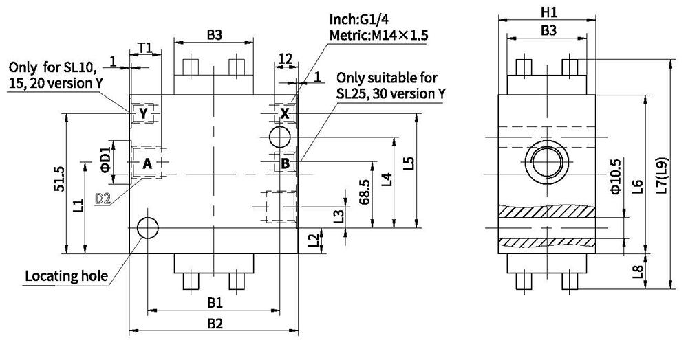
| Type | Size | B1 | B2 | B3 | D1 | T1 | H1 | L1 | L2 | L3 | L4 | L5 | L6 | L7 | L8 | L9 | Inch | Metric D2 |
| SV | 10 | 66.5 | 85 | 40 | 34 | 14 | 43 | 27.5 | 18.5 | 10.5 | 33.5 | 49 | 80 | 116 | 18 | 116 | G1/2 | M22x1.5 |
| 15 | 79.5 | 100 | 55 | 42 | 16 | 57 | 36.5 | 17.5 | 13 | 50.5 | 67.5 | 95 | 135 | 20 | 146 | G3/4 | M27x2 | |
| 20 | 79.5 | 100 | 55 | 47 | 18 | 57 | 36.5 | 17.5 | 13 | 50.5 | 67.5 | 95 | 135 | 20 | 146 | G1 | M33x2 | |
| 25 | 97 | 120 | 70 | 56 | 20 | 75 | 54.5 | 15.5 | 20.5 | 73.5 | 89.5 | 115 | 173 | 29 | 179 | G11/4 | M42x2 | |
| 30 | 97 | 120 | 70 | 61 | 22 | 75 | 54.5 | 15.5 | 20.5 | 73.5 | 89.5 | 115 | 173 | 29 | 179 | G11/2 | M48x2 | |
| SL | 10 | 66.5 | 85 | 40 | 34 | 14 | 43 | 22.5 | 18.5 | 10.5 | 33.5 | 49 | 80 | 116 | 18 | 116 | G1/2 | M22x1.5 |
| 15 | 79.5 | 100 | 55 | 42 | 16 | 57 | 30.5 | 17.5 | 13 | 50.5 | 72.5 | 100 | 140 | 20 | 151 | G3/4 | M27x2 | |
| 20 | 79.5 | 100 | 55 | 47 | 18 | 57 | 30.5 | 17.5 | 13 | 50.5 | 72.5 | 100 | 140 | 20 | 151 | G1 | M33x2 | |
| 25 | 97 | 120 | 70 | 56 | 20 | 75 | 54.5 | 15.5 | 20.5 | 84 | 99.5 | 125 | 183 | 29 | 189 | G11/4 | M42x2 | |
| 30 | 97 | 120 | 70 | 61 | 22 | 75 | 54.5 | 15.5 | 20.5 | 84 | 99.5 | 125 | 183 | 29 | 189 | G11/2 | M48X2 |
Note: Dimension L7 suits valve with opening pressure types "1" and "2", and dimension L9 suits valve with opening pressure types "3".
Ordering code: for threaded connection valve type SV/SL series30