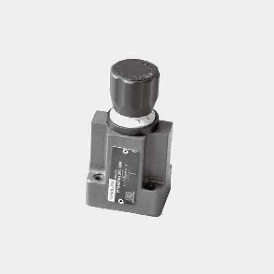
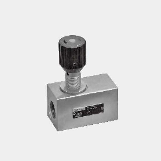
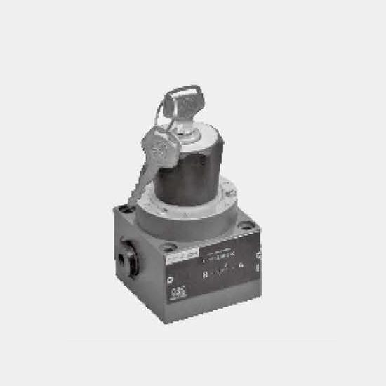
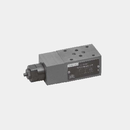
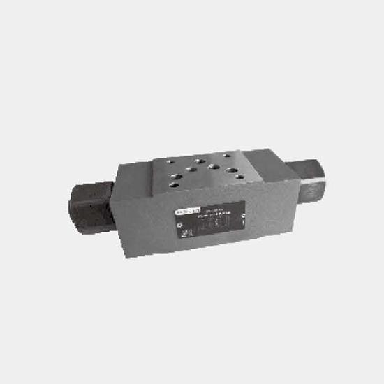
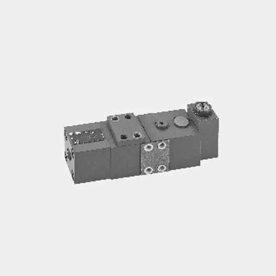
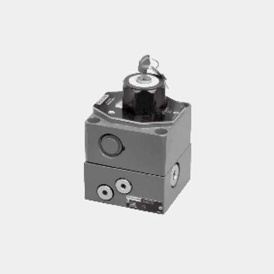
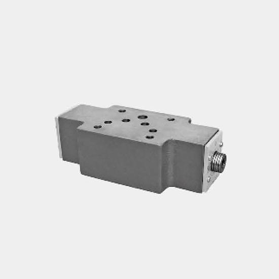
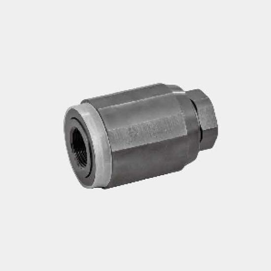
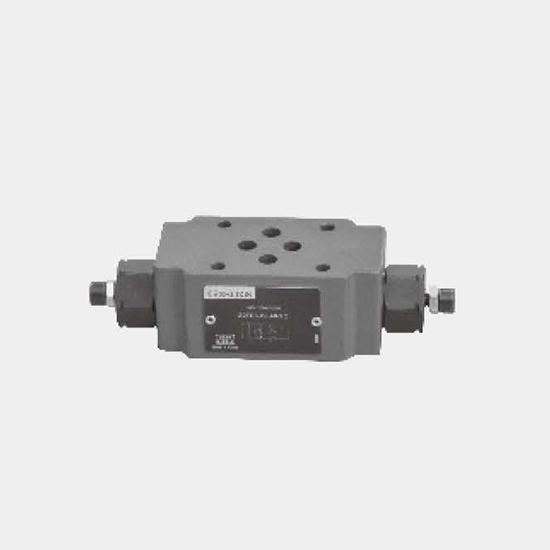
Flow control valve, type 2FRM6 and rectifier plate, type Z4S6
Product Detail
Function and configurations
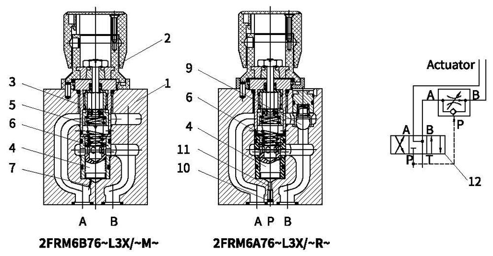
Flow control valve of type 2FRM is a two-way flow control valve, used for maintaining a constant flow and is independent of pressure and temperature. It consists of housing(1), knob rotary(2), orifice(3), pressure compensator(4), optional check valve(9).
Flow control valve 2FRM6B~L3X/~M
Flow from A to B is throttled at throttle channel (5).
Throttle cross-section is varied by turning the knob rotary(2). To avoid effects of pressure at port B on constant flow, a compensator (4) is fitted. Spring (6) separately compress the compensator (4) and orifice (3) tightly.
Spring (6) compresses the compensator (4) tightly to maintain it open when no fluid flows through the valve. Once the fluid flows across the valve, the pressure in port A applies a force to pressure compensator (4) through the orifice (7). The pressure compensator (4) moves into the compensating position until the force is balanced. If the pressure in port A rises, the compensator (4) moves to its closing direction until force is balanced again. Due to the compensator (4) continuous action, a constant flow is obtained.
2FRM6A~L3X/~R
The function of this valve is basically the same as that of valve type 2FRM6B~L3X/~R. However, pressure compensator (4) of this type of valve is connected with port P (11) so that pressure compensator (4) can be closed by external pressure. Any pressure in port P through the orifice (10) can make the compensator (4) closed against the force of compression spring (6). When the directional valve (12) acts, fluid flows from P to B, control is achieved as type 2FRM6B.
This flow controls the valve with the external pressure compensator which can be closed. It only works by controlling the inlet flow.
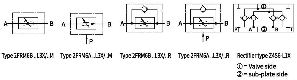
Symbols
Ordering code
. For flow control valve
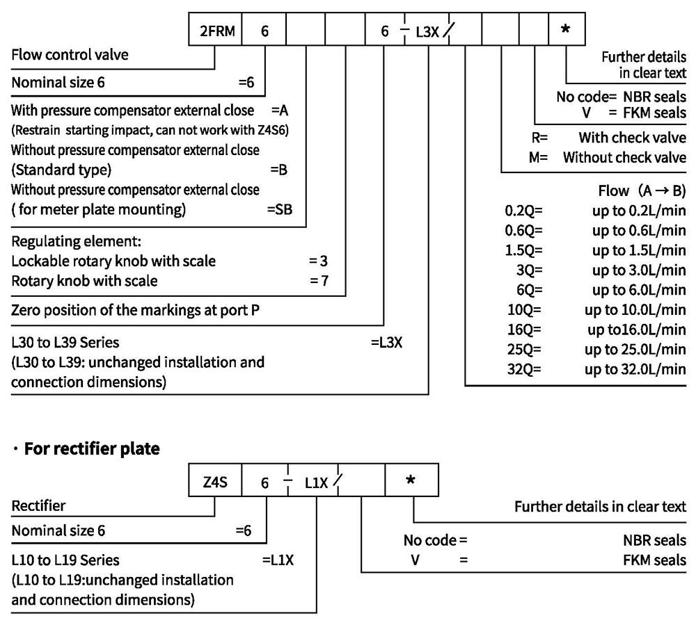
Technical data
·Flow control valve
| Max. operating pressure at port A bar | 315 | |||||||||
| Pressure differential ΔP for free return flow B to A | See characteristic curves | |||||||||
| Minimum pressure differential bar | 6 to 14 | |||||||||
| Pressure stabiity up to P=315 bar % | ±2(Qmax) | |||||||||
| Flow-rate | Qmax L/min | 0.2 | 0.6 | 1.5 | 3 | 6 | 10 | 16 | 25 | 32 |
| Qmin to 100bar mL/min | 15 | 15 | 15 | 15 | 25 | 50 | 70 | 100 | 250 | |
| Qmin to 315bar mL/min | 25 | 25 | 25 | 25 | 25 | 50 | 70 | 100 | 250 | |
| Fluid | Mineral oil suit, Phosphoric acid ester | |||||||||
| Fluid temperature range ℃ | -20 to+80 | |||||||||
| Viscosity range m㎡/s | 10 to 800 | |||||||||
| Degree of contamination | Maximum permissible degree of fluid contamination: Class 9. NAS 1638 or 20/18/15, ISO4406 | |||||||||
| Installation position | Optional | |||||||||
| Circumstances temperature range ℃ | -20 to+50 | |||||||||
| Weight | 2FRM6A...2FRM6B... kg | Approx.1.3 | ||||||||
| 2FRM6SB... kg | Approx.1.5 | |||||||||
·Rectifier
| Nominal flow bar | 320 |
| Maximum operating pressure bar | To 210 |
| Cracking pressure bar | 0.7 |
| Weight kg | Approx.0.9 |
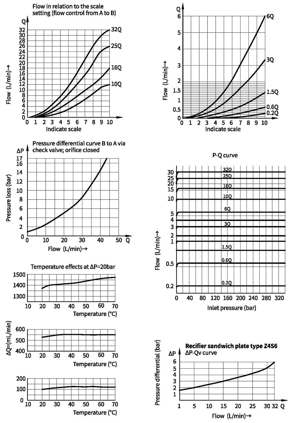
Characteristic curves (Measured at oil=40°C +5°C, using HLP46)
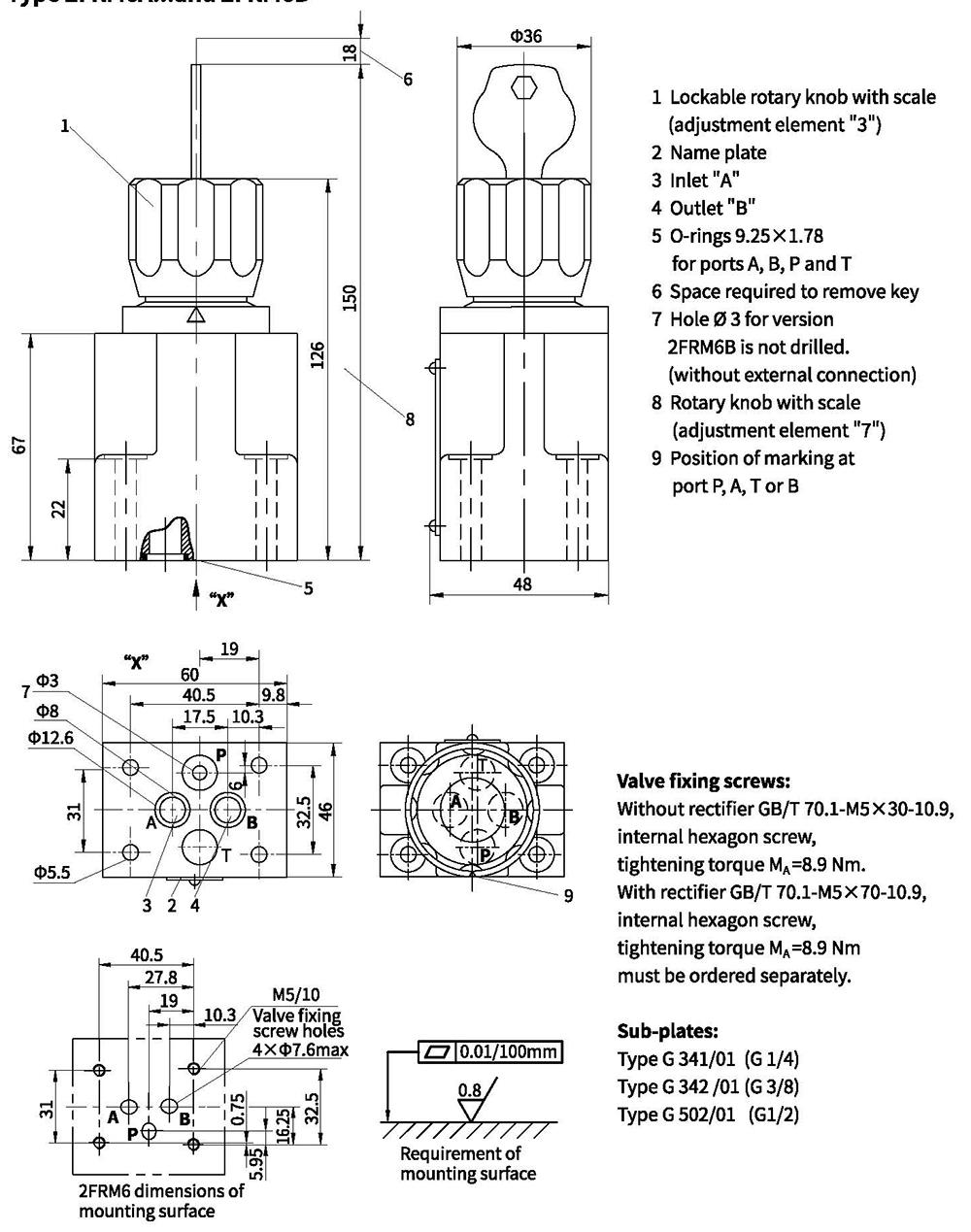
Unit dimensions
Type 2FRM6A...and 2FRM6B
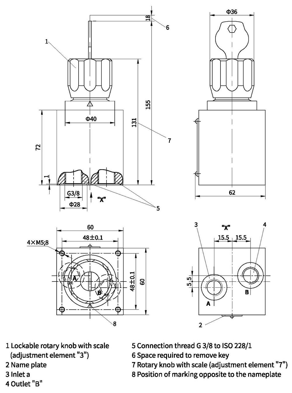
Unit dimensions
Type 2FRM6SB
Unit dimensions
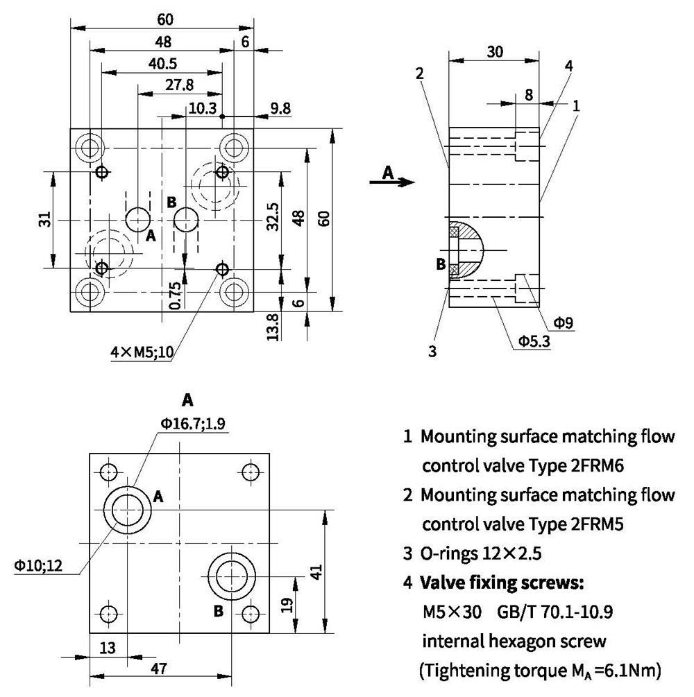
Transition plate AG5075
Note:
The transition plate type AG5075 is specially designed for mounting flow control valve type 2FRM6B..-L3X/.. onto an existing porting pattern of flow control valve type 2FRM5-30/..
Unit dimensions
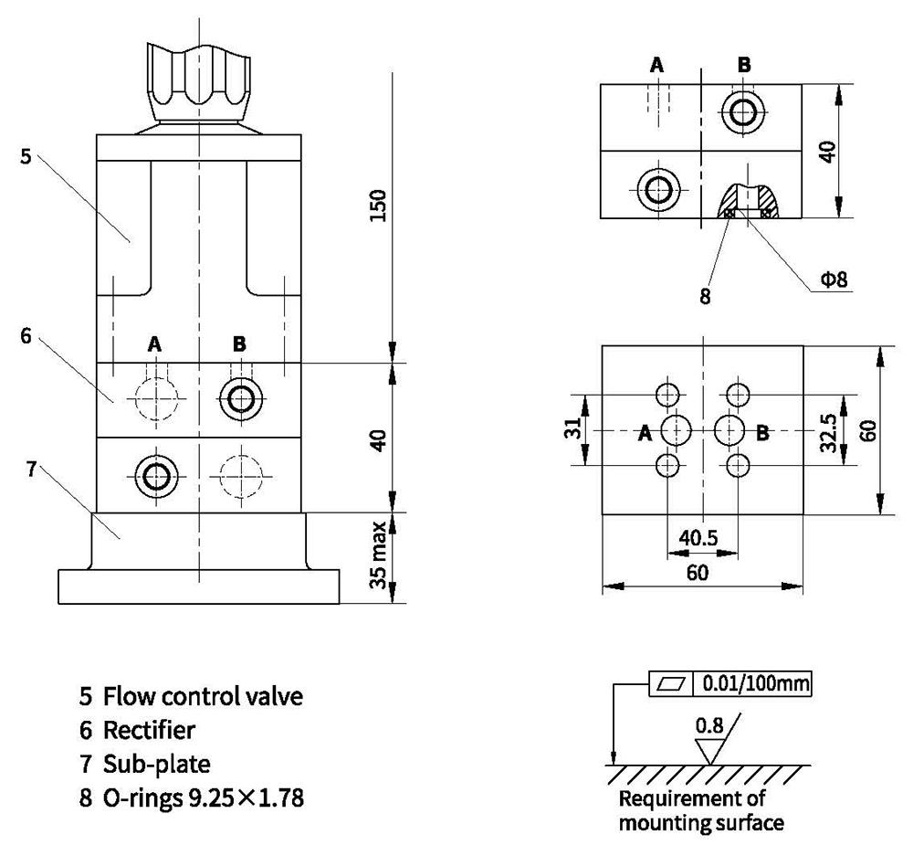
Rectifier type Z4S6-L1X
Caution:
Rectifier sandwich plate type Z4S6-L1X can not be used in conjunction withflow control valve type 2FRM6A..-L3X/.. with built-in external connection ofthe pressure compensator.