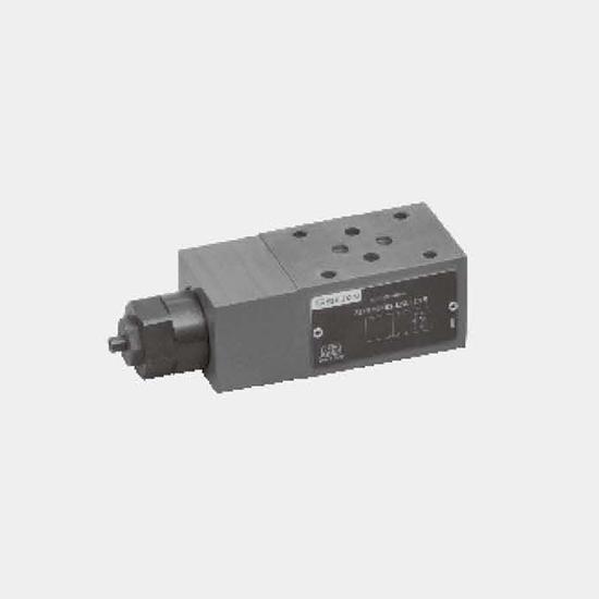
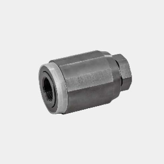
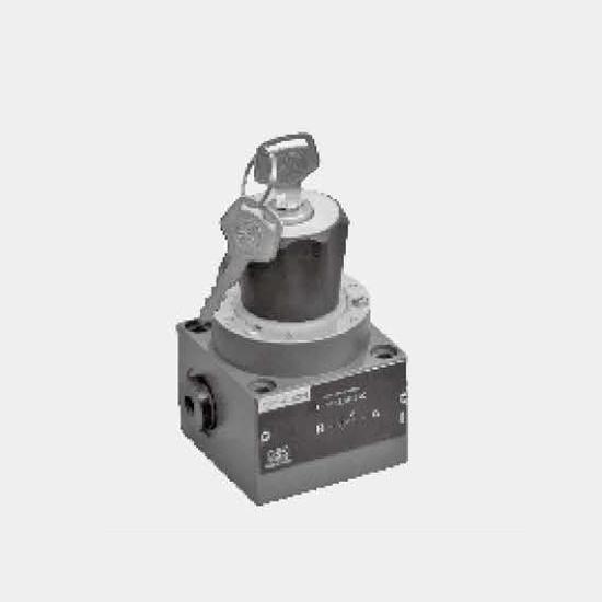
Function and configurationCheck-Q-meters are used to prevent runaway of hydraulic cylinder and motor in hydraulic system. They can also prevent pipe bursting.Check-Q-meter basically consists of the ho...
Product Detail
Function and configuration
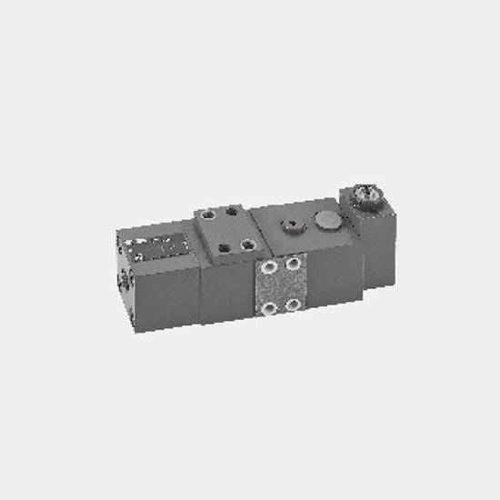
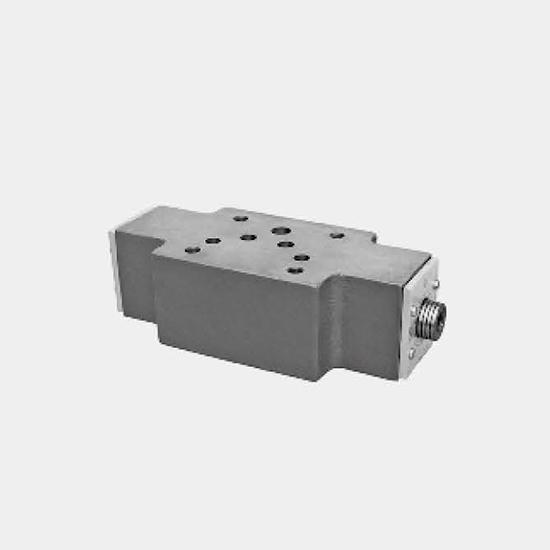
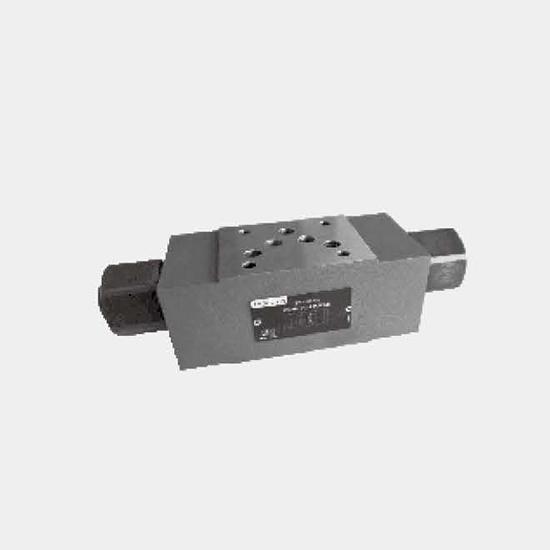
Check-Q-meters are used to prevent runaway of hydraulic cylinder and motor in hydraulic system. They can also prevent pipe bursting.
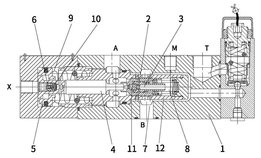
Check-Q-meter basically consists of the housing (1), main poppet (2), pilot part (3), steel ball (11), pilot spool (4), spring seat (5) and damping (6). When load is lifted, fluid flows from A to B, the main spool (2) is opened. If pipe is cracked caused by the system, main spool (2) closes immediately because chamber (8) is connected with load pressure.
Lowering the load (circuit examples)
The direction of flow is from B to A. Port A is connected to tank via the directional valve. The piston rod side of the cylinder has a flow applied which corresponds to the working conditions. The relationship between the control pressure at port X and the load pressure at port B = 1:20.
When the control pressure is reached, the main spool opens. Via the control spool (4) the pilot stage (3) and steel ball (11) are lifted off its seat and chamber (8) is de-compressed via its internal hole and port A to tank. At the same time the load pressure in port B is no longer applied to chamber (8), this is due to the longitudinal movement of the pilot stage (3) within the main spool. The main poppet (2) is thereby unloaded. The reverse side of the control spool (4) at the main poppet (2), lies against the collar edge of the damping spool (5).
In order to open the main poppet, the pressure in the port X is decided by the spring in the chamber (9). When the valve open, the pressure is 20bar, and fully open it is 60bar.
The opening cross-section for flow control increases progressively. It is created by the successive opening of radial hole in the sleeve (12) and the main poppet (2) land.
The relationship between the control pressure, cracking pressure and differential pressure determines the flow to the actuator via the connection of B to A. Thus uncontrolled running away of the actuator is prevented.
The controlled lowering procedure is not affected even if there is a pipe burst between the directional valve and port A.
Guidelines for influencing the opening and closing times of the check-Q-meter.
Throttling of the opening sequence is via orifice (6) in the control spool (4) and both sides of the damping spool (5). The orifice (6) is protected by sieves (10).
The closing movement of the check-Q-meter is virtually unthrottled.
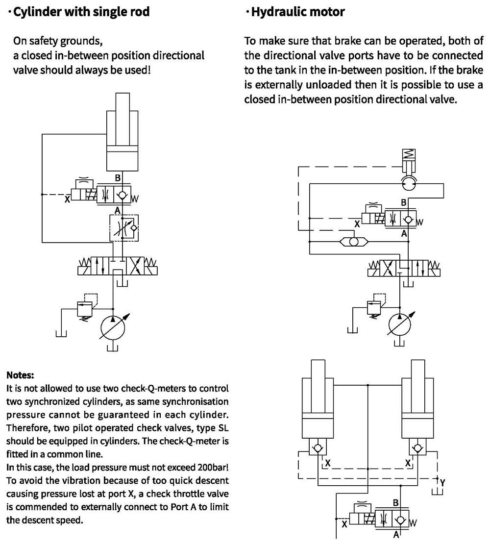
When being used in conjunction with cylinders the control line to port X can be fitted with a throttle check valve (meter-out control) to influence the closing sequence.
When being used in conjunction with motors a throttle check valve should not be fitted in the control line to port X. In this case it is recommended that the control time of the directional valve are influenced.
Curcuit examples
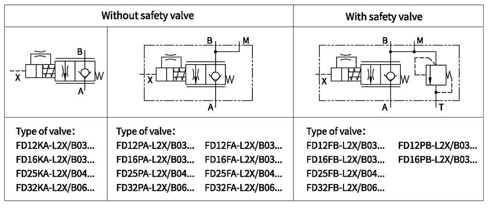
Symbols
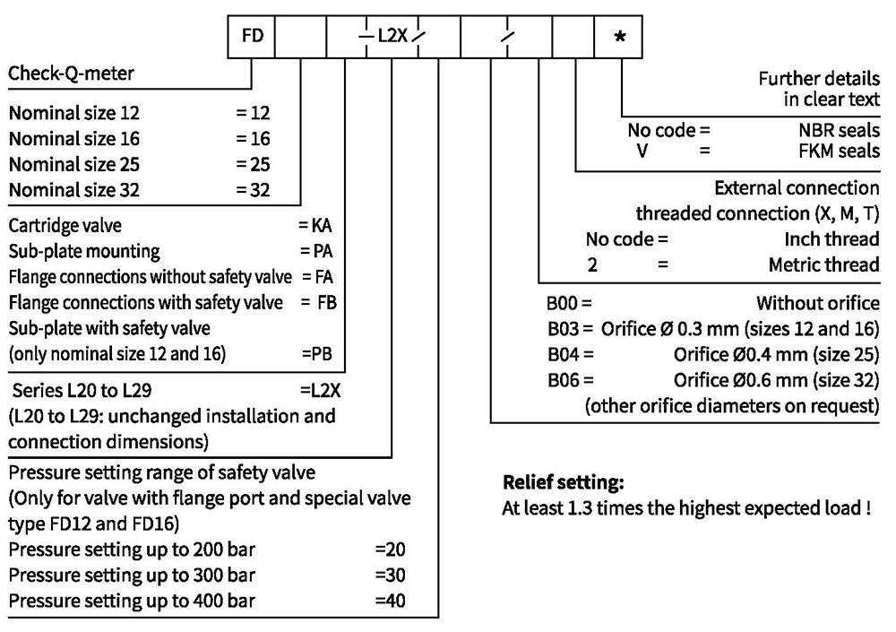
Ordering code
Technical data
| Operating pressure, ports A, X bar | to 350 |
| Operating pressure, port B bar | to 420 |
| Pilot pressure, port X bar (flow control range) | min.20~60,max.350 |
| Cracking pressure, A to B bar | 2 |
| Setting pressure for secondary bar pressure relief valve | to 400 |
| Flow-rate L/min | 80(size 12),200(size 16),320(size 25),560(size 32) |
| Area ratio of the pre-opening | poppet seat area = /1 |
| Fluid | Mineral oil,phosphate ester |
| Fluid temperature range ℃ | -20 to+80 |
| Viscosity range m㎡/s | 10 to 800 |
| Degree of contamination | aximum permissible degree of fluid contamination: Class 9. NAS 1638 or 20/18/15, ISO4406 |
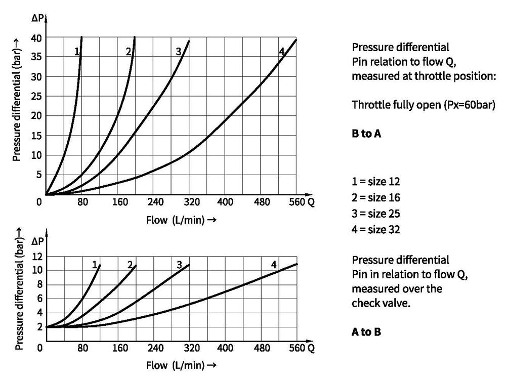
Characteristic curves (Measured at oil =40°C +5°C, using HLP46)
Unit dimensions
. Installation in manifolds (cartridge valve)
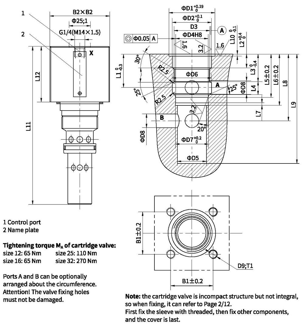
| Type | B1 | B2 | D1 | D2 | D3 | D4 | D5 | D6 | D7 | D8 | D9 | T1 | L1 | L2 | L3 | L4 | L5 |
| FD12KA | 48 | 70 | 54 | 46 | M42x2 | 38 | 34 | 46 | 38.6 | 16 | M10 | 16 | 39 | 16 | 32 | 15.5 | 50.5 |
| FD16KA | 48 | 70 | 54 | 46 | M42x2 | 38 | 34 | 46 | 38.6 | 16 | M10 | 16 | 39 | 16 | 32 | 15.5 | 50.6 |
| FD25KA | 56 | 80 | 60 | 54 | M52x2 | 48 | 40 | 60 | 48.6 | 25 | M12 | 19 | 50 | 19 | 39 | 22 | 65 |
| FD32KA | 66 | 95 | 72 | 65 | M64x2 | 58 | 52 | 74 | 58.6 | 30 | M16 | 23 | 52 | 19 | 40 | 25 | 71 |
| Type | L6 | L7 | L8 | L9 | L10 | L11 | L12 | valve fixing screws/Tighting torque | MA(Nm) | Weight |
| FD12KA | 60 | 3 | 78 | 128 | 2.3 | 191 | 65 | 4 pcs M10x70 GB/T70.1-10.9 | 69 | 3.5kg |
| FD16KA | 60 | 3 | 78 | 128 | 2.3 | 191 | 65 | 4 pcs M10x70 GB/T70.1-10.9 | 69 | 3.5kg |
| FD25KA | 80 | 4 | 105 | 182 | 2.3 | 253 | 75 | 4 pcs M12x80 GB/T70.1-10.9 | 120 | 5.6kg |
| FD32KA | 85 | 4 | 115 | 198 | 2.3 | 289 | 94 | 4 pcs M16x100 GB/T70.1-10.9 | 295 | 8.0kg |
Unit dimensions
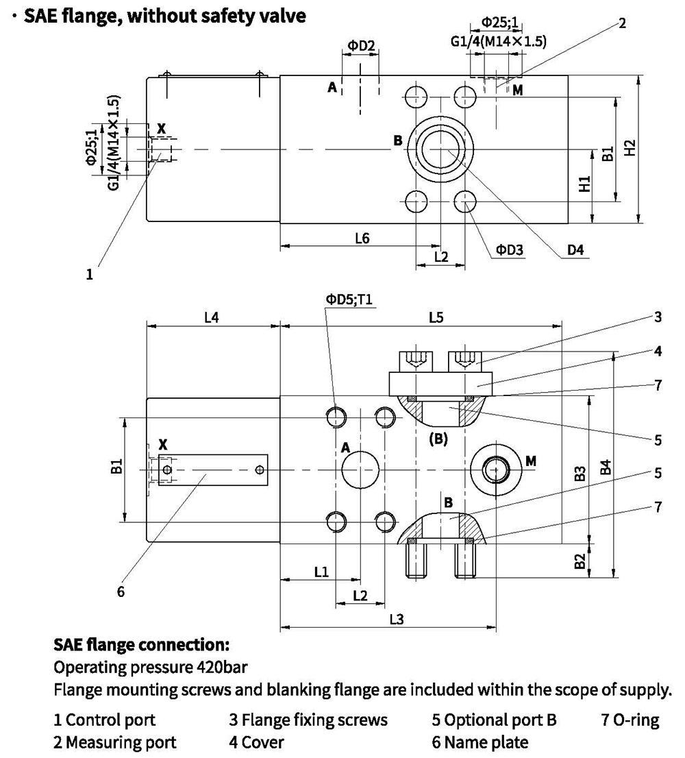
| Type | B1 | B2 | B3 | B4 | D1 | D2 | D3 | D4 | D5 | H1 | H2 | L1 | L2 | L3 | L4 |
| FD12FA | 50.8 | 16.5 | 72 | 110 | 43 | 18 | 10.5 | 18 | M10 | 36 | 72 | 39 | 23.8 | 105 | 65 |
| FD16FA | 50.8 | 16.5 | 72 | 110 | 43 | 18 | 10.5 | 18 | M10 | 36 | 72 | 39 | 23.8 | 105 | 65 |
| FD25FA | 57.2 | 14.5 | 90 | 132 | 50 | 25 | 13.5 | 25 | M12 | 45 | 90 | 50 | 27.8 | 148 | 75 |
| FD32FA | 66.7 | 20 | 105 | 154 | 56 | 30 | 15 | 30 | M14 | 50 | 105 | 52 | 31.8 | 155 | 94 |
| Type | L5 | L6 | T1 | Weight | O-ring(7) | Valve fixing screws |
| FD12FA | 140 | 78 | 15 | 7.2kg | 25x3.5 | 4 pcs M10x100 GB/T70.1-10.9 |
| FD16FA | 140 | 78 | 15 | 7.2kg | 25x3.5 | 4 pcs M10x100 GB/T70.1-10.9 |
| FD25FA | 200 | 105 | 18 | 16kg | 32.92x3.53 | 4 pcs M12x120 GB/T70.1-10.9 |
| FD32FA | 215 | 115 | 21 | 23kg | 37.7x3.53 | 4 pcs M14x140 GB/T70.1-10.9 |
Unit dimensions
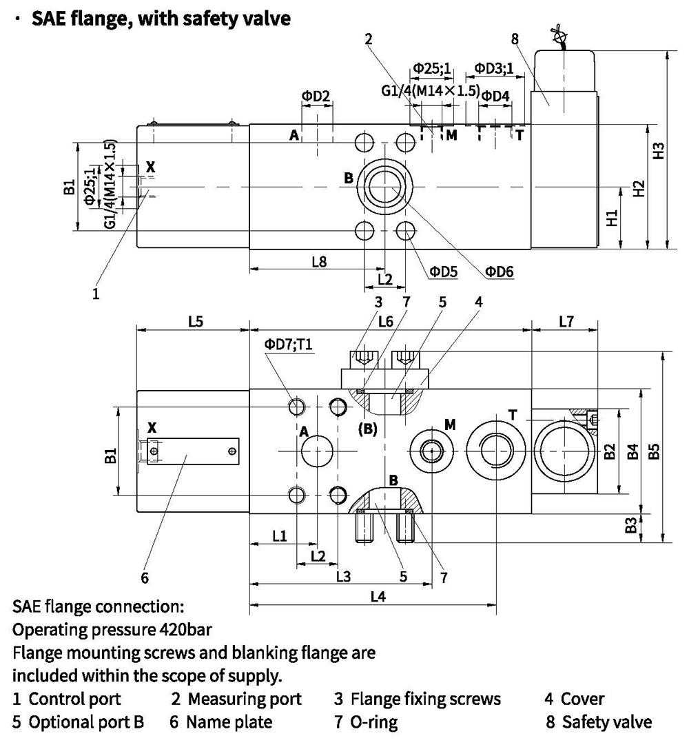
| Type | B1 | B2 | B3 | B4 | B5 | D1 | D2 | D3 | D4 | D5 | D6 | D7 | H1 | H2 | H3 | L1 | |
| Inch | Metric | ||||||||||||||||
| FD12FB | 50.8 | 49 | 16.5 | 72 | 110 | 43 | 18 | 34 | G1/2 | M22x1.5 | 10.5 | 18 | M10 | 36 | 72 | 118 | 39 |
| FD16FB | 50.8 | 49 | 16.5 | 72 | 110 | 43 | 18 | 34 | G1/2 | M22x1.5 | 10.5 | 18 | M10 | 36 | 72 | 118 | 39 |
| FD25FB | 57.2 | 78 | 14.5 | 90 | 132 | 50 | 25 | 42 | G3/4 | M27x2 | 13.5 | 25 | M12 | 45 | 90 | 145 | 50 |
| FD32FB | 66.7 | 78 | 20 | 105 | 154 | 56 | 30 | 42 | G3/4 | M27x2 | 15 | 30 | M14 | 50 | 105 | 145 | 52 |
| Type | L2 | L3 | L4 | L5 | L6 | L7 | L8 | T1 | Weight | O-ring(7) | valve fixing screws |
| FD12FB | 23.8 | 105 | 141.5 | 65 | 162 | 38 | 78 | 15 | 9kg | 25x3.5 | 4 pcs M10x100 |
| FD16FB | 23.8 | 105 | 141.5 | 65 | 162 | 38 | 78 | 15 | 9kg | 25x3.5 | 4 pcs M10x100 |
| FD25FB | 27.8 | 148 | 198 | 75 | 225 | 50 | 105 | 18 | 20kg | 32.92x3.53 | 4 pcs M12x120 |
| FD32FB | 31.8 | 155 | 215 | 94 | 240 | 50 | 115 | 21 | 28kg | 37.7x3.53 | 4 pcs M14x140 |
Unit dimensions
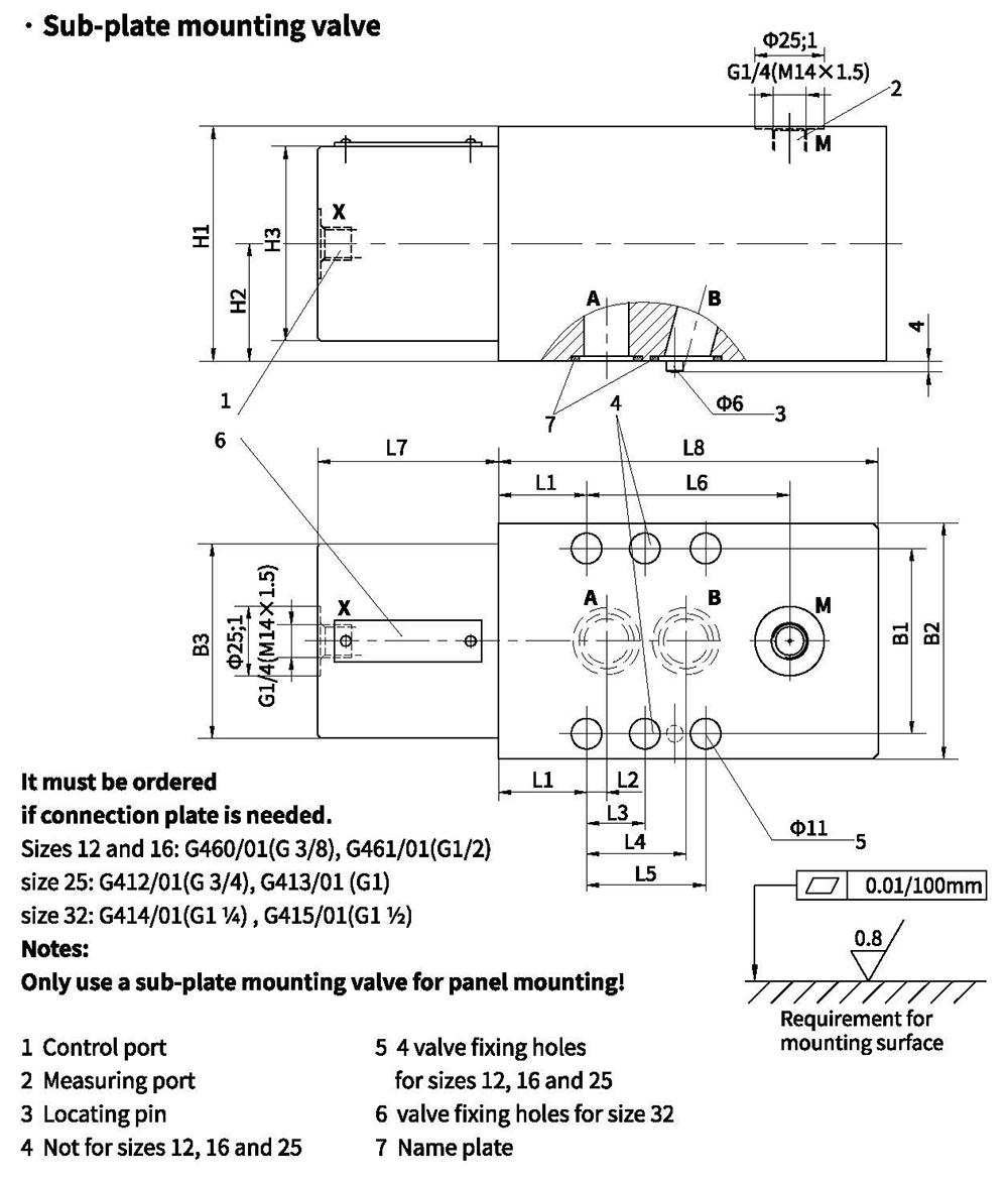
| Type | B1 | B2 | B3 | H1 | H2 | H3 | L1 | L2 | L3 | L4 | L5 | L6 |
| FD12PA | 66.7 | 85 | 70 | 85 | 42.5 | 70 | 31.8 | 7.2 | - | 35.8 | 42.9 | 73.2 |
| FD16PA | 66.7 | 85 | 70 | 85 | 42.5 | 70 | 31.8 | 7.2 | - | 35.8 | 42.9 | 73.2 |
| FD25PA | 79.4 | 100 | 80 | 100 | 50 | 80 | 38.9 | 11.1 | - | 49.2 | 60.3 | 109.1 |
| FD32PA | 96.8 | 120 | 95 | 120 | 60 | 95 | 35.3 | 16.7 | 42.1 | 67.5 | 84.2 | 119.7 |
| Type | L7 | L8 | Valve fixing screws/tighting torque | MA(Nm) | Weight | O-ring(7) |
| FD12PA | 65 | 140 | 4 pcs M10 x100 GB/T70.1-10.9 | 75 | 9.3kg | 21.3x2.4 |
| FD16PA | 65 | 140 | 4 pcs M10x100 GB/T70.1-10.9 | 75 | 9.3kg | 21.3x2.4 |
| FD25PA | 75 | 200 | 4 pcs M10x120 GB/T70.1-10.9 | 75 | 18kg | 29.82x2.62 |
| FD32PA | 94 | 215 | 6 pcs M10x140 GB/T70.1-10.9 | 75 | 28kg | 38x3 |
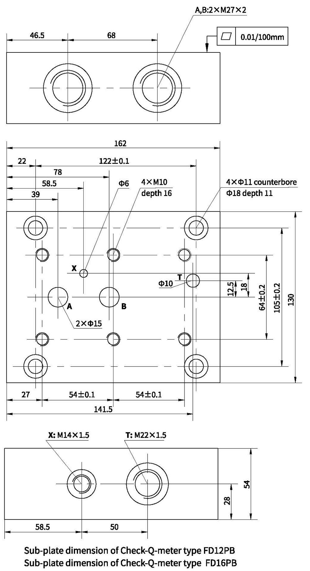
Unit dimensions
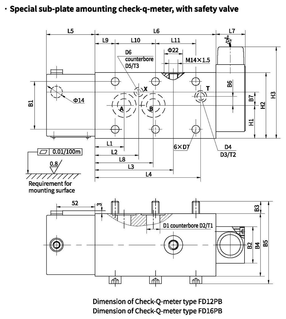
| Type | B1 | B2 | B3 | B4 | B5 | B6 | B7 | D1 | D2 | D3 | D4 | D5 | D6 | D7 |
| FD12PB | 64 | 49 | 16 | 84 | 11 | 12.5 | 18 | 18 | 32 | 15.7 | 10 | 12.2 | 6 | 10.5 |
| FD16PB | 64 | 49 | 16 | 84 | 11 | 12.5 | 18 | 18 | 32 | 15.7 | 10 | 12.2 | 6 | 10.5 |
| Type | H1 | H2 | H3 | L1 | L2 | L3 | L4 | L5 | L6 | L7 | L8 | L9 | L10 | L11 |
| FD12PB | 44 | 88 | 126 | 39 | 58.5 | 105 | 141.5 | 65 | 162 | 38 | 78 | 27 | 54 | 54 |
| FD16PB | 44 | 88 | 126 | 39 | 58.5 | 105 | 141.5 | 65 | 162 | 38 | 78 | 27 | 54 | 54 |
| Type | T1 | T2 | T3 | Weight | Fixing screws | O-ring( 7) | ||
| FD12PB | 2.7 | 1.9 | 1.4 | 10kg | 4pcs M10x100 GB/T70.1-10.9 | 25x3.53 | 12x2 | 9.25x1.78 |
| FD16PB | 2.7 | 1.9 | 1.4 | 10kg | 25x3.53 | 12x2 | 9.25x1.78 | |
Unit dimensions
· Sub-plate for special check-Q-meter with safety valve