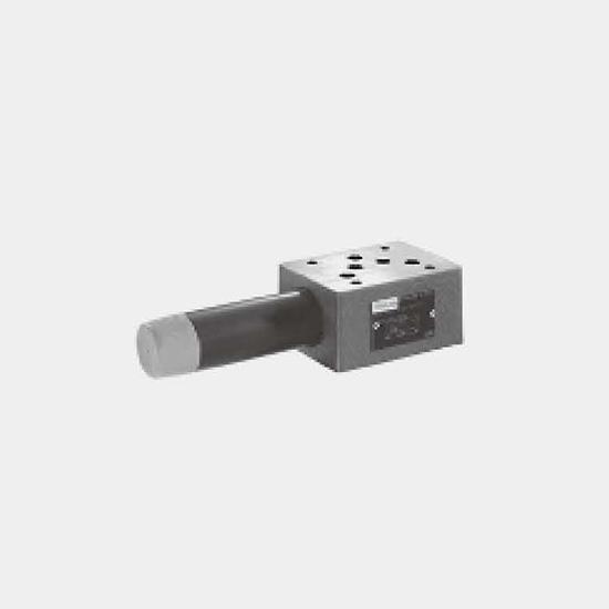
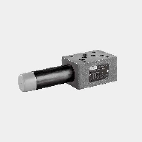
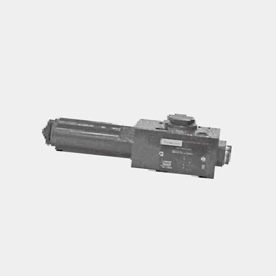
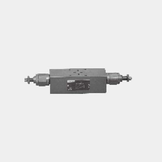
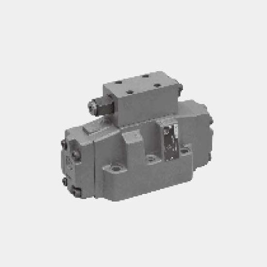
Function and configurationThe pressure reducing valve type ZDR 10 D.. is a 3-way direct operated valve of sandwich plate design with a pressure relief function on the secondary side. It is used to red...
Product Detail
Function and configuration
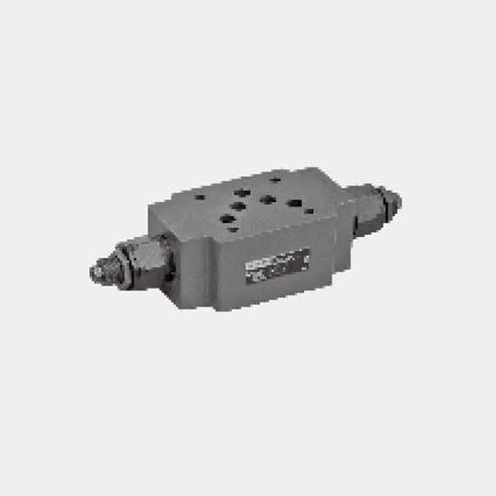
The pressure reducing valve type ZDR 10 D.. is a 3-way direct operated valve of sandwich plate design with a pressure relief function on the secondary side. It is used to reduce the system pressure.
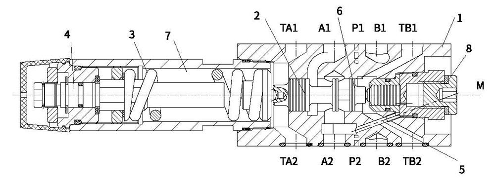
The pressure reducing valve basically consists of the housing (1), the control spool (2), a compression spring (3), and the adjustment (4) as well as an optional check valve.
The secondary pressure is set by the pressure adjustment element (4).
Model "DA"
At rest, the valve is normally open, and fluid can flow unhindered from port A1 to port A2. The pressure in port A2 is at the same time via the control line (5) present at the spool area opposite to the compression spring (3). When the pressure in port A2 exceeds the pressure level set at the compression spring (3), the control spool (2) moves into the control position against the compression spring (3) and holds the set pressure in port A2 constant. The control pressure and pilot oil are taken from port A2 via control line (5).
If the pressure in port A2 rises still further due to external forces, the control spool (2) is moved still further towards the compression spring (3). This causes a flow path to be opened at port A2 via control land (6) on the control spool (2) and housing (1) to tank (port TB). Sufficient fluid then flows to tank to prevent any further rise in pressure.
The spring chamber (7) is always drained to tank externally via port TA.
A pressure gauge connection (8) permits the secondary pressure at the valve to be monitored.
It is only possible to fit a check valve for free flow in ports A2 to A1 in version "DA".
Models "DP" and "DB"
In model "DP", the pressure is reduced in port P1. The control pressure and the pilot oil is taken internally from port P1. In model "DB", the pressure in port P1 is reduced, and the pilot oil taken from port B.
Attention!
When the directional valve is in the switched position P to A, pressure in port B must not exceed the set secondary pressure. Otherwise, pressure in port A will be reduced.
If used without a directional valve, TA and TB must be interconnected (e.g. in the cover plate).
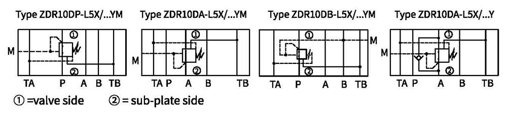
Type ZDR10DA...-L5X/...YM...
Symbols
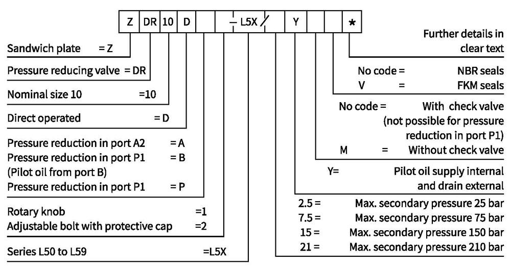
Ordering code
Technical data
| Fluid | Mineral oil suitable for NBR and FKM seal |
| Phosphate ester for FKM seal | |
| Fluid temperature range ℃ | -30 to +80 (NBR seal) |
| -20 to +80 (FKM seal) | |
| Viscosity range m㎡/s | 10 to 800 |
| Degree of contamination | Maximum permissible degree of fluid contamination: Class 9.NAS 1638 or 20/18/15, ISO4406 |
| Max.operating pressure (inlet) bar | up to 315 |
| Max.secondary pressure (output) bar | up to 25; up to 75; up to 150; up to 210 |
| Back pressure bar | 150 |
| Max.flow-rate L/min | 80 |
| Weight Kg | Approx.2.8 |
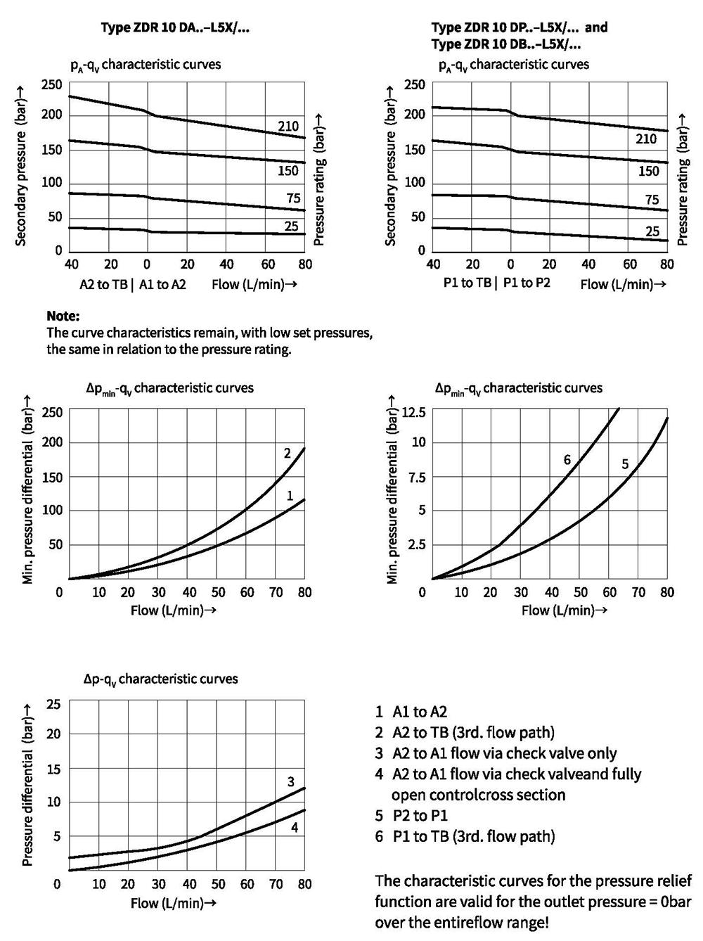
Characteristic curves (Measured at oil =40°C +5°C, using HLP46)
Unit dimensions
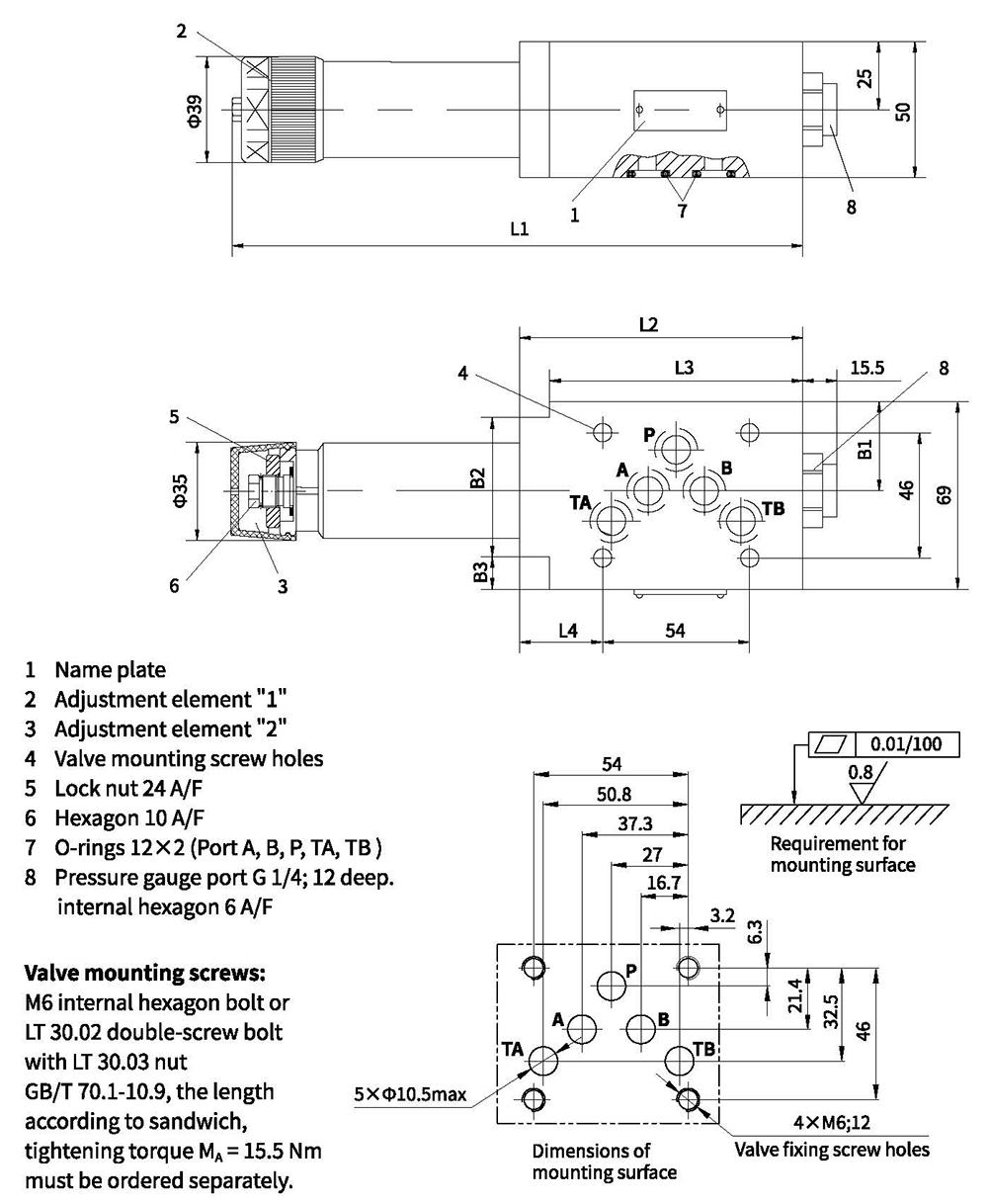
| Model | L1 | L2 | L3 | L4 | L5 | L6 | B1 | B2 | B3 |
| "DA" | 254 | 230 | 210 | 104 | 93 | 31.5 | 32.9 | 51 | 12 |
| "DB" and "DP" | 242 | 218 | 198 | 91 | - | 18.5 | 35 | - | - |