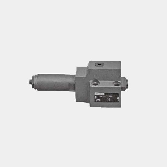
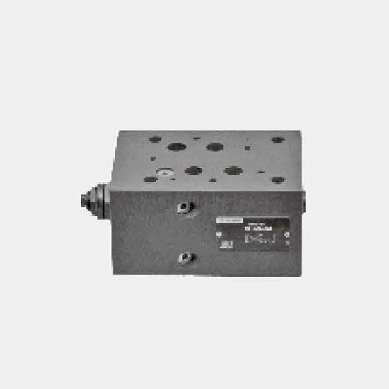
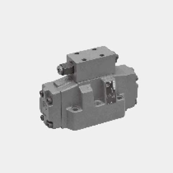
Function and configurationG...DBW type Explosion-proof operated relief valve is used for restricting and discharging system pressure. It mainly consists of main valve (1) with plug-in (3), pilot valve...
Product Detail
Function and configuration
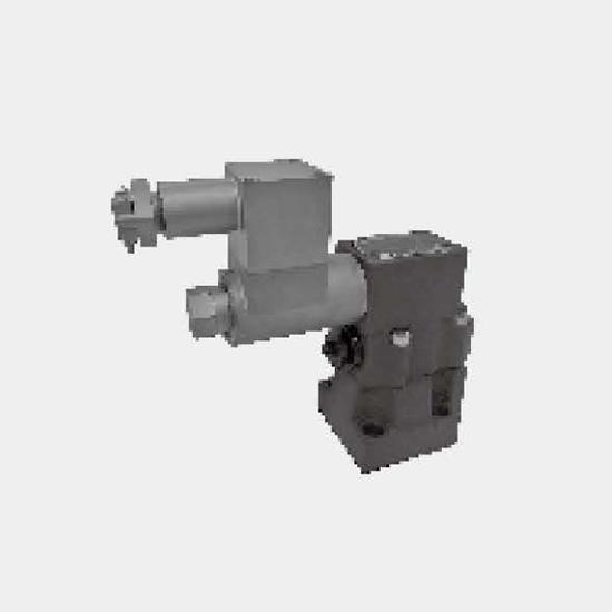
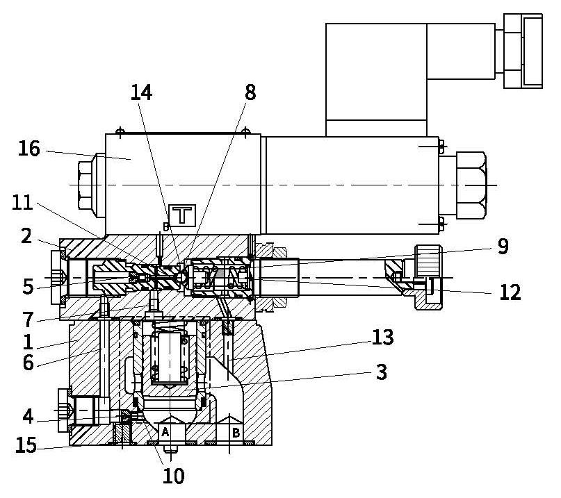
G...DBW type Explosion-proof operated relief valve is used for restricting and discharging system pressure. It mainly consists of main valve (1) with plug-in (3), pilot valve (2) with pressure regulating element and magnetic exchange valve (16).
The pressure of channel A acts on the main spool (3), meanwhile, pressure is applied via control line (6) and (7) with orifice (4) and (5) on the spring loaded side of the main spool (3) and on the ball (8) in the pilot operated valve(2). If the pressure in channel A rises excess the setting value at the spring (9), the ball (8) opens against the spring (9). As for the internal control forms, signal is given by control oil (10) and (6) supplied by channel A. The oil from the spring loaded side of the main spool (3), via control line (7), orifice(11), and ball (8), then flows into spring chamber (12). About internal drain - type DBW..L5X..Y-, oil flows via control line(14) into the tank. In virtue of the orifice (4) and (5), the pressure drop arises at the main spool (3), and the connection from port A to port B is open while the setting operation pressure maintain invariable. The pressure relief valve may unload or shift the different pressure (second rated pressure value) in virtue of external control port X (15).
The basis function of pressure relief valve type DBW is the same with pressure relief valve type DB, the difference is that valve type DBW operates unloading via a built-on directional valve(16).
Pressure relief valves with switching shock damping (sandwich )
Type DBW../..S..R12
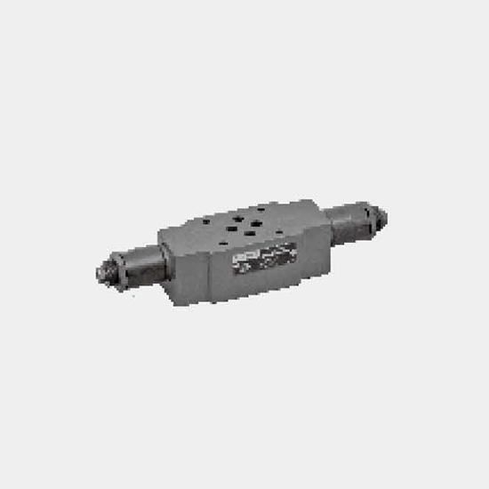
Due to switching shock damping (17), the connection from B2 to B1 opens delayed to avoid the impact of the peak pressure and decompression in the return line. It is fitted between pilot valve (2) and the directional valve (16).
The relief degree (decompression impact) is determined by the size of the orifice (18). Orifice ∅1.2mm is recommended. (ordering detail: ..R12 ..).
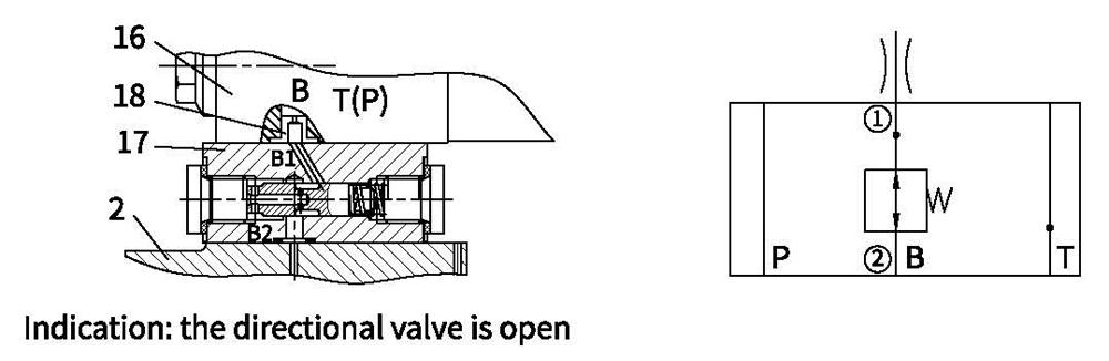
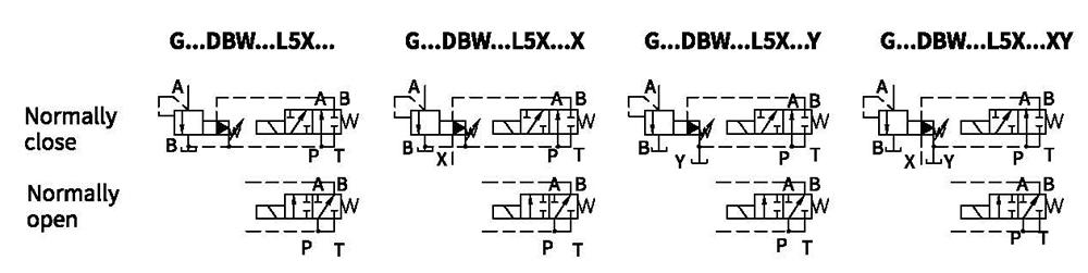
Symbols
Technical data
| Fixing position | Optional | |||||
| Weight | G...DBW...10 | G...DBW...15 | G...DBW...20 | G...DBW...25 | G...DBW...30 | |
| Sub-plate mounting G...DBW kg | Approx.5.6 | - | Approx.6.5 | - | Approx.7.9 | |
| Threaded connection G...DBW..G.. kg | Approx.7.9 | Approx.7.8 | Approx.7.7 | Approx.8.5 | Approx.8.4 | |
| Switching shock damping kg | Approx.0.6 | |||||
| Techinical parameters of directional valve | See G...WE6 type Explosion-proof magnetic exchange valve, G...3WE6A9 is used as the normally closed type, G...3WE6B9 is used as the normally opened type. | |||||
| Fluid | Mineral oil - suitable for NRB and FRMseal | |||||
| phosphate ester-suitable for FKM seal | ||||||
| Fluid temperature range ℃ | -30to+80 (NRB seal) | |||||
| -20 to+80 (FKM seal) | ||||||
| Viscosity range m㎡/s | 10 to 800 | |||||
| Degree of contamination | Maximum permissible degree of fluid contamination: Class9. NAS 1638 or 20/18/15, ISO4406. | |||||
| Max.operating pressure | PortA, B,X,P bar | 350 | ||||
| PortY or T DBW bar | 210 | |||||
| Max. back pressure bar | 50;100;200;315;350 | |||||
| Min. bar | Interrelated with Q (refer to the curve) | |||||
| Sizes | 10 | 15 | 20 | 25 | 30 | |
| Max.flowrate | sub-plate mounting L/min | 250 | - | 500 | - | 650 |
| threaded connection L/min | 250 | 500 | 500 | 500 | 650 | |
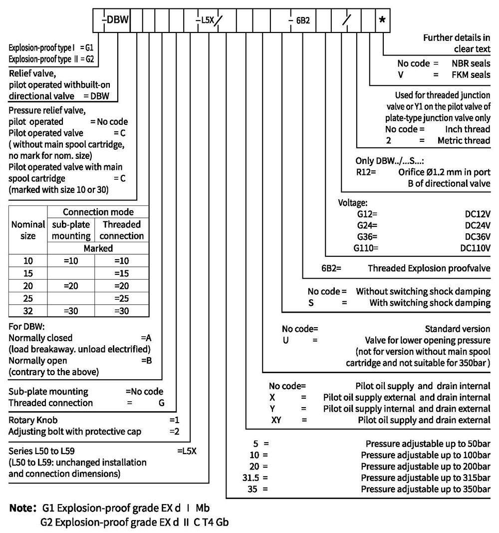
Ordering code
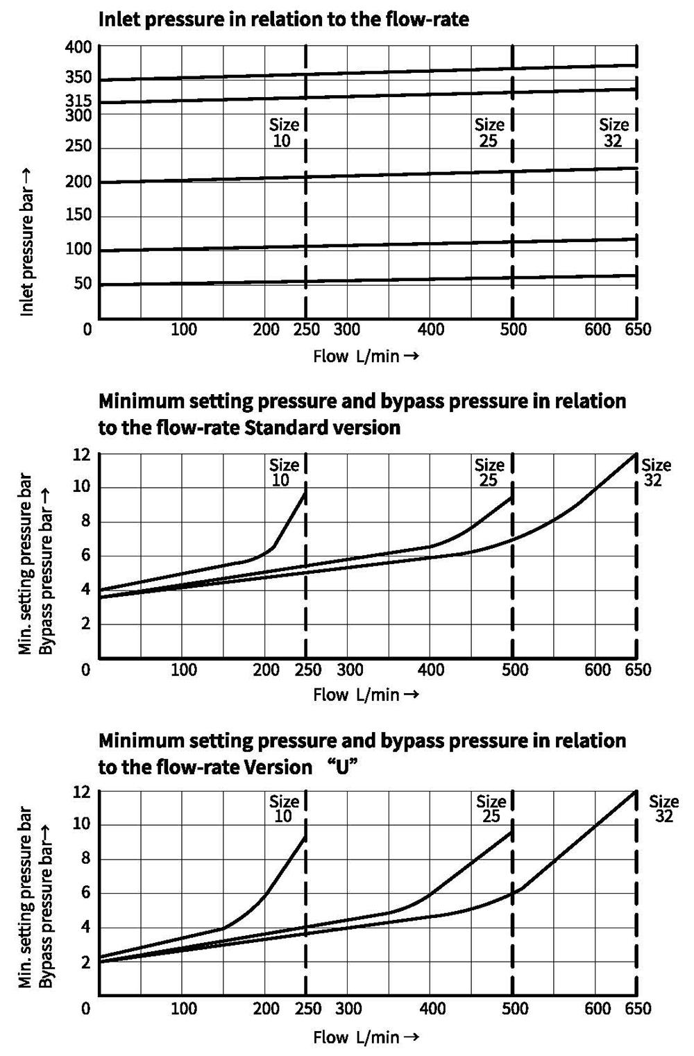
Characteristic curves (Measured at oil =40°C +5°C, using HLP 46)
The characteristic curves are measured with external pilot oil drain at zero pressure. With internal pilotoil drain, the inlet pressure at port B should be added to the value presented as curves.
Unit dimensions
Sub-plate mounting
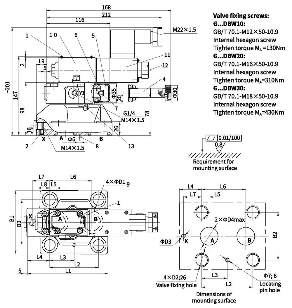
| Type | L1 | L2 | L3 | L4 | L5 | L6 | L7 | L8 | L9 | B1 | B2 | D1 | D2 | D3 | D4 | O-ring(A,B) | O-ring(X) |
| G...DBW 10 | 91 | 53.8 | 22.1 | 27.5 | 22.1 | 47.5 | 0 | 25.5 | 2 | 78 | 53.8 | 14 | M12 | 6 | 12 | 17.12x2.62 | 9.25x1.78 |
| G...DBW 20 | 116 | 66.7 | 33.4 | 33.3 | 11.1 | 55.6 | 23.8 | 22.8 | 10.5 | 100 | 70 | 18 | M16 | 6 | 22 | 28.17x3.53 | 9.25x1.78 |
| G...DBW 30 | 147.5 | 88.9 | 44.5 | 41 | 12.7 | 76.2 | 31.8 | 20 | 21 | 115 | 82.6 | 20 | M18 | 7 | 30 | 34.52x3.53 | 9.25x1.78 |
Unit dimensions
Threaded connection
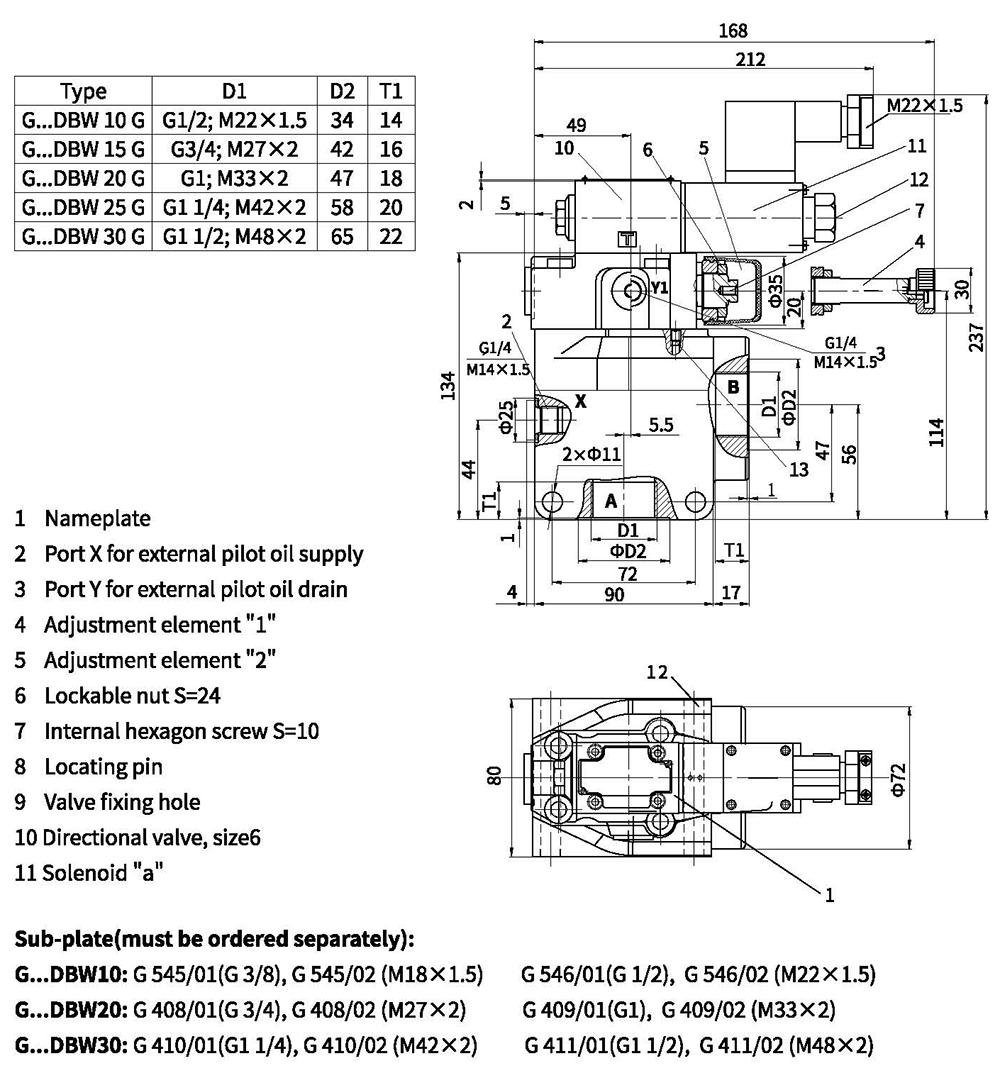
Unit dimensions
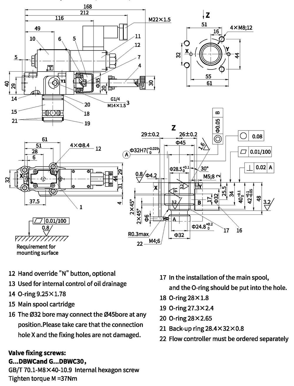
With main spool valve(G...DBWC10or30)or without main spool valve(G...DBWC)