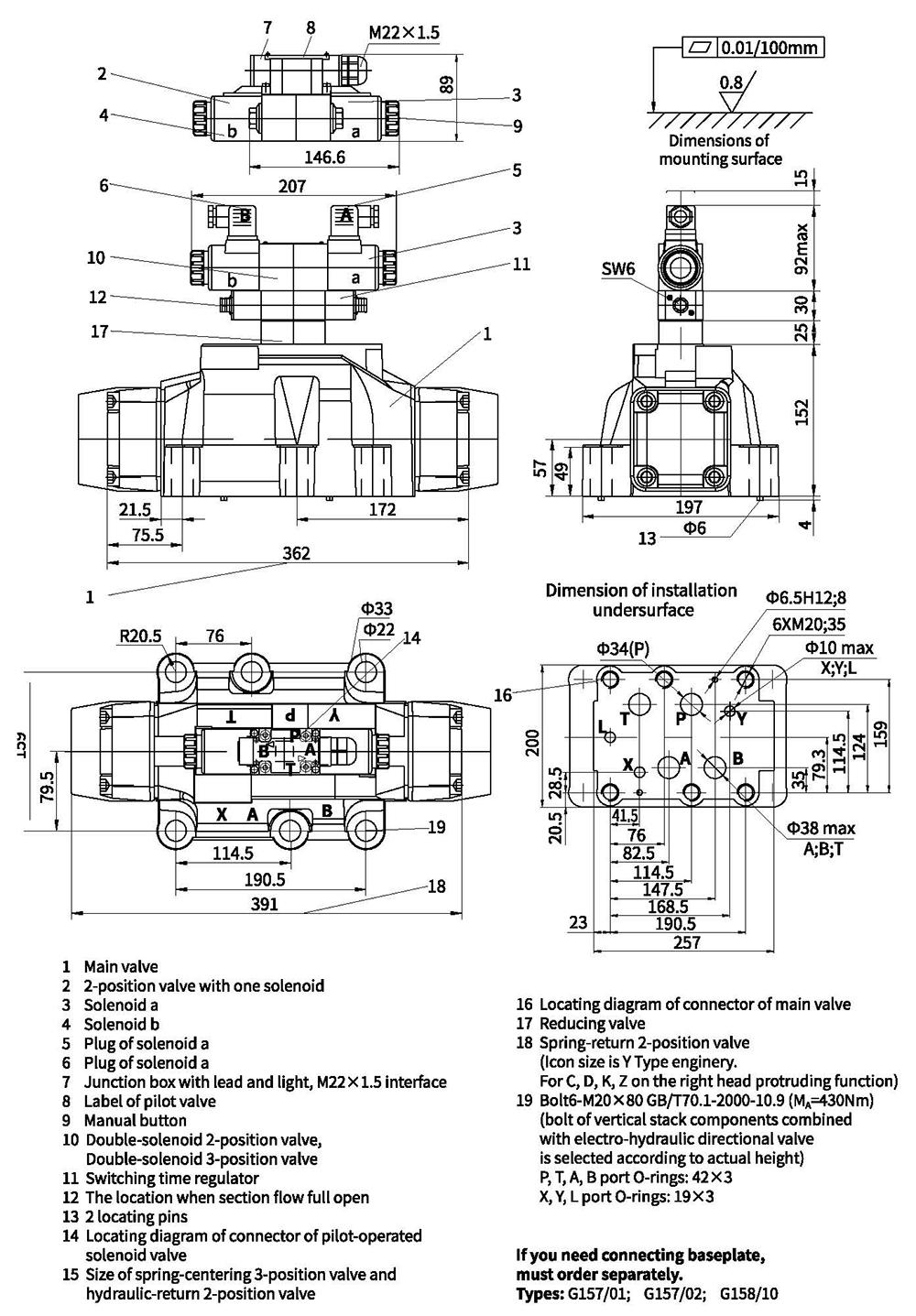
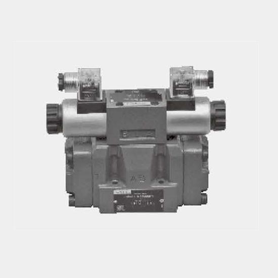
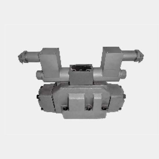
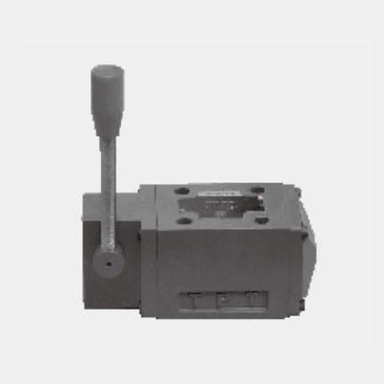
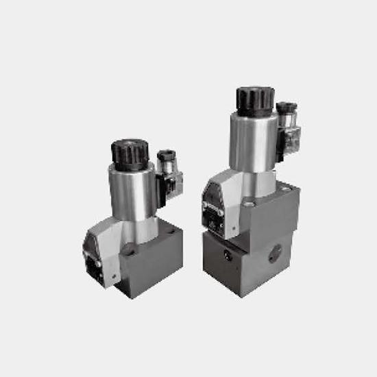
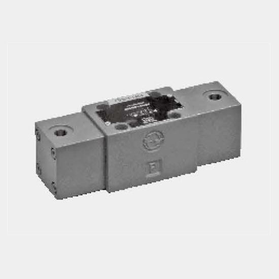
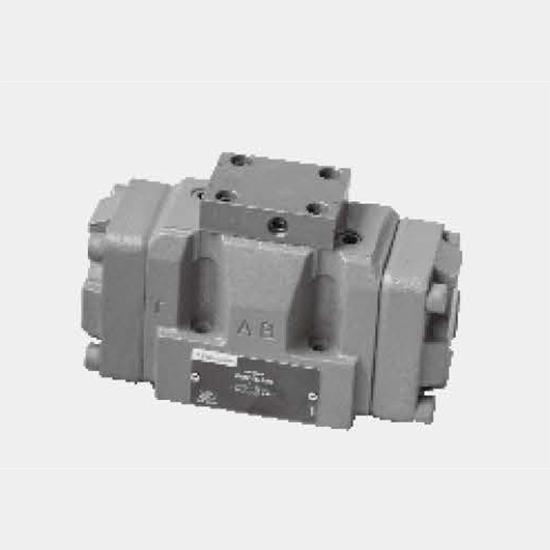
Function and configurationsValves of type WEH are directional spool valves with electro-hydraulic operation. They control the start, stop and direction of a flow.Solenoid valves used for pilot control...
Product Detail
Function and configurations
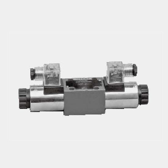
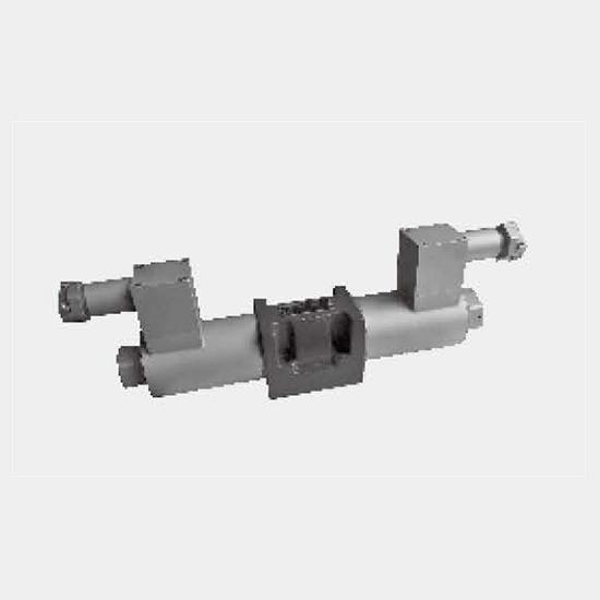
Valves of type WEH are directional spool valves with electro-hydraulic operation. They control the start, stop and direction of a flow.
Solenoid valves used for pilot control are with wet AC or DC solenoid available; Main valves apply spring centering and spring reset or hydraulic reset; with or without Switching time adapters; with or without stroke regulators for main valves; back pressure valves may be installed in main valves; throttle may be installed; pressure reducing valves may be installed when working pressure exceeds 250bar.
The valve mainly consists of main valve body(1), main valve spool(2), one(or two)reset spring (3) with one(or two) pilot solenoid valve of solenoid. Main valve spools(2) is held in the neutral or in the initial position either by the springs or by means or pressure. Pilot solenoid valves (4) may select wet-type AC or DC solenoids(5) and pilot solenoid valves are able to control the switching of main valves.
There are four patterns on supply and drain of control oil, see the function diagram.
Following are descriptions of various types of valves:
Main valves are 4/3-way directional valve with spring centring of the control spool.
Main valve spool(2) is held in the neutral position by means of two return springs. And two spring chambers(6) are connected with tank through pilot solenoid valves.
When one of the two ends of the main control spool (2) is pressurised with pilot pressure, the spool is moved to the switched position. The required ports in the valve are then opened to flow.
When the pilot pressure is removed, the spring on the opposite side to the pressurised spool area causes the spool to return to its neutral or initial position.
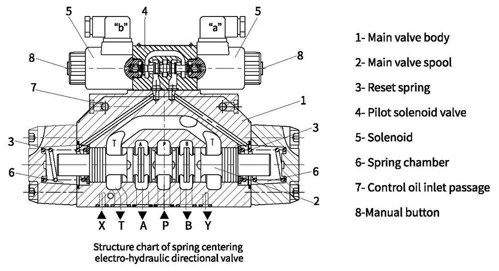
Function and configurations
2/4 way directional valves
( this kind of valve has four different structures and Types)
Type WEH.../...
This kind of pilot valve and main valve have a reset spring each, resetting by spring force.
Type WEH...H.../...
This kind of valve has a reset spring, making pilot valve spool stay in initial position. Main valve spools change directions under effect of pressure oil.
Type WEH...H.../O...
This kind of valve has two solenoids. There are no reset springs in pilot valves and main valves, thus using solenoids and pressure oil to make pilot valves and main valve spools change directions. Therefore, at least one solenoid shall be under working state.
Type WEH...H.../OF...
This kind of valve has two solenoids and locators which makes pilot valve spools stay in working position(impulse valves). Main valve spools have no locating devices , moving downward to corresponding working positions under effect of pressure oil.
Structure 2, 3 and 4 aforesaid are hydraulic reset. Main valve spools can stay in the working position only under the effect of pressure oil.
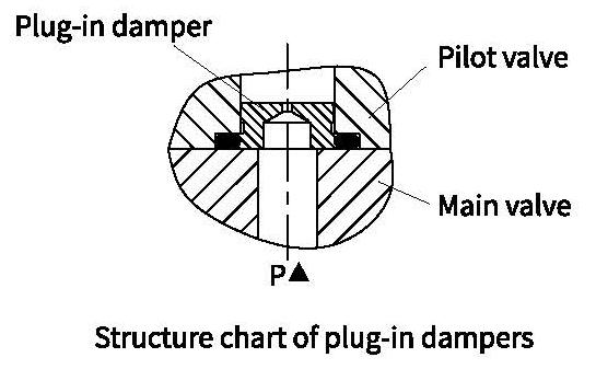
Throttle insert:
The use of a throttle insert is required if the pilot oil supply in the P channel of the pilot valve is to be limited. This throttle is inserted in the P channel of the pilot valve.
Function and configurations
Pilot oil supply:
1、Type WEH10
(1) Conversion between internal supply and external supply:
P channel on the top of main valve bodies with M6 bolt(2) is external supply and with M6 bolt (2) dismounted is internal supply.
(2) Conversion between internal drain and external drain:
Dismounting plug screws(1) and installing M6 bolt(2) is external drain; dismounting M6 bolt(2) is internal drain.
2、Type WEH16
(1) Conversion between internal supply and external supply:
Dismounting plug screw(10) form P channel on the sidesurface of main valves and installing M6 bolt(9) is internal supply. Dismounting M6 plug bolt(9) is internal supply.
(2) Conversion between internal drain and external drain:
Dismounting plug screw(10) form T hole on the top of main valves and installing M6 plug bolt(9) is internal drain. Dismounting M6 bolt(9) is external drain.
3、Type WEH25
(1) Conversion between internal supply and external supply:
P channel on the top of main valve bodies with M6 bolt(6) is external supply and with M6 bolt (6) dismounted is internal supply.
(2) Conversion between internal drain and external drain:
Dismounting plug bolt(6) from T hole on the top of main valves and installing M6 plug bolt(9) is internal drain. Dismounting M6 bolt(9) is external drain.
4、Type WEH32
(1) Conversion between internal supply and external supply:
Dismounting plug screw(9) from P hole on the undersurface of main valves and installing M6 bolt(9) is internal supply. Dismounting M6 plug bolt(9) is internal supply.
(2) Conversion between internal drain and external drain:
Dismounting plug screw(9) from T hole on the top of main valves and installing M6 plug bolt(9) is internal drain. Dismounting M6 bolt(9) is external drain.
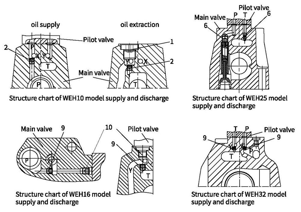
Attention:
X port on base plates must be blocked when internal supply occurs and Y port on base plates must be blocked when internal drain occurs.
Function and configurations
Switching time adjustment:
In order to influence the switching time of the main valve a double throttle check valve has to be fitted between pilot valves and main valves to control oil supply from pilot valves into main valve spools, thus adjusting the switching time of main valves.
Regulating bolt rotation clockwise, the time for switching of main valves is long, otherwise the time is short.
The throttle check valve has two kinds: meter-in throttling and meter-out throttling. If there is a need of changing meter-in throttling into meter-out throttling, just install the valve after rotating 180° around the longitudinal axis again and then install pilot valves.
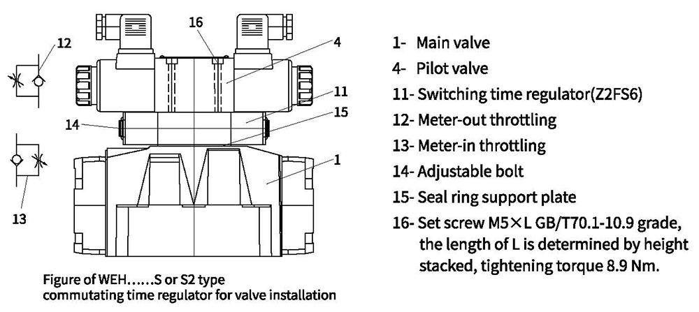
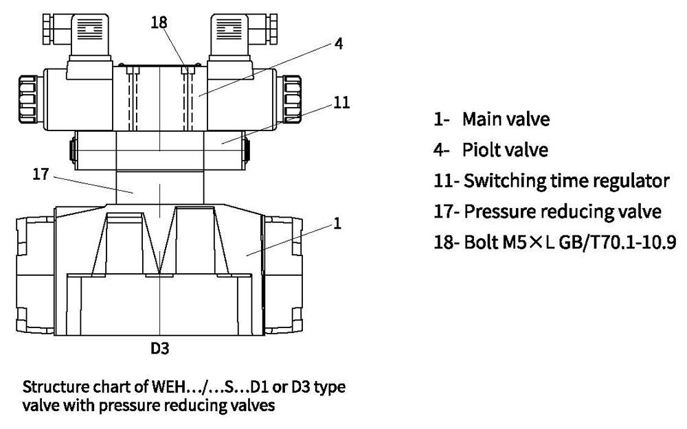
Pressure reducing valves:
The pressure reducing valve (8) must be used if the pilot pressure is higher than 250 bar (for type 4WEH 22 ...: 210 bar). Pressure reducing ratio of constant-ratio pressure reducing valves (D1) is 1:0.66.
Pressure reducing pressure of constant-ratio pressure reducing valves shall not exceed 40 bar.
Minimum control pressure of technical specifications shall improve 1/0.66=1.515 after installing bottom plate pressure reducing valves.
Constant-ratio pressure reducing valves shall not be used when controlling internal oil drain and using back pressure valves (P0.45) with control pressure decreased to 3 bar.
Function and configurations
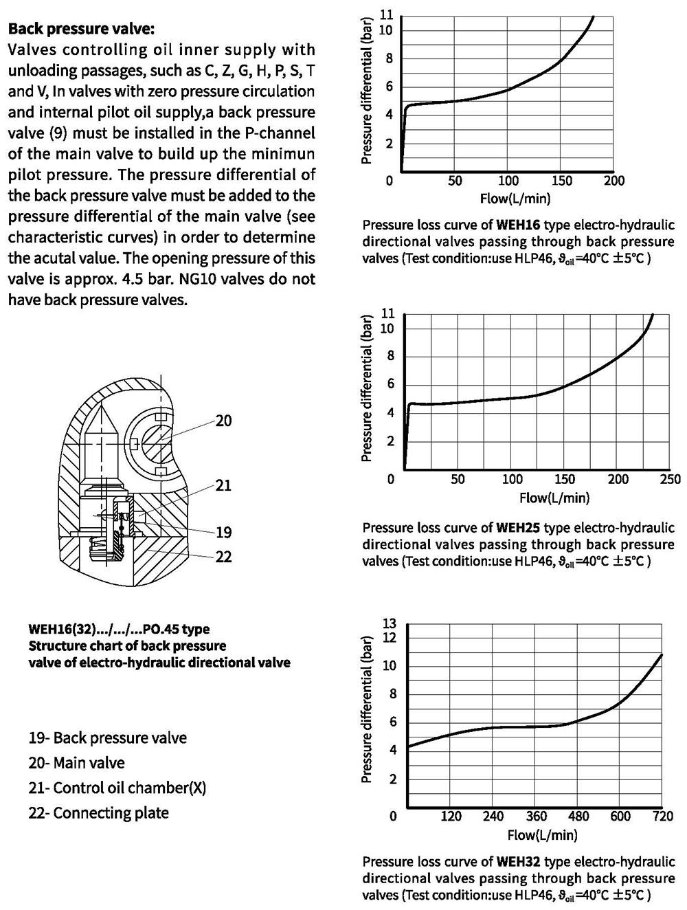
Ordering code
Note:
1、For function of WEH10 such as C, Z, F, G, H, P, T, V, etc., if applying control oil internal supply, please try to use external add enough back pressure on return port T (port Y shall not have back pressure) to ensure valves can reverse properly.
2、Pressure reducing valves shall be applied when control pressure exceeds 250 bar.
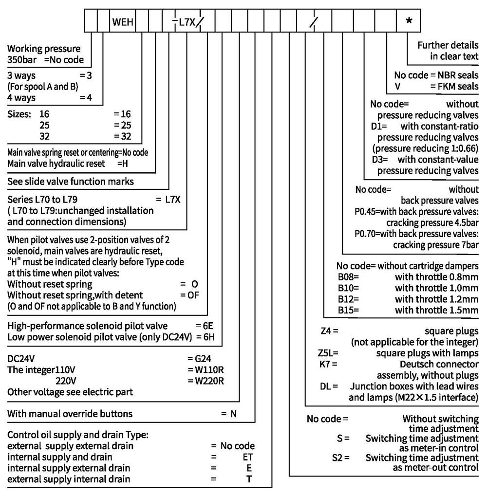
Ordering code
Note:
1、For function of WEH16-32 such as C, Z, F, G, H, P, T, V, etc, if applying control oil internal supp, please try to use external add enough back pressure on return port T( port Y shall not have back pressure) to ensure valves can reverse properly.
2、Pressure reducing valves shall be applied when control pressure exceeds 250bar.
Symbols
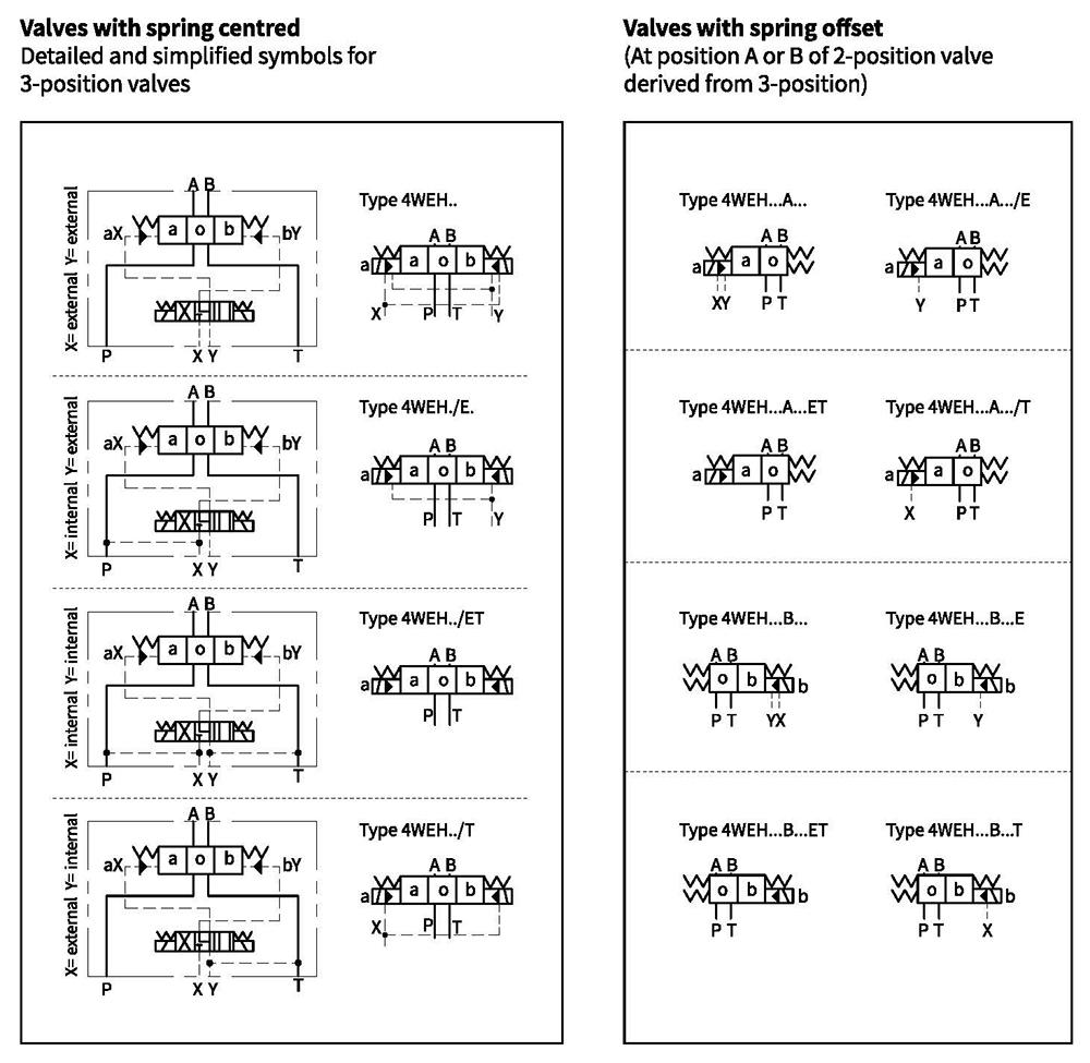
Symbols
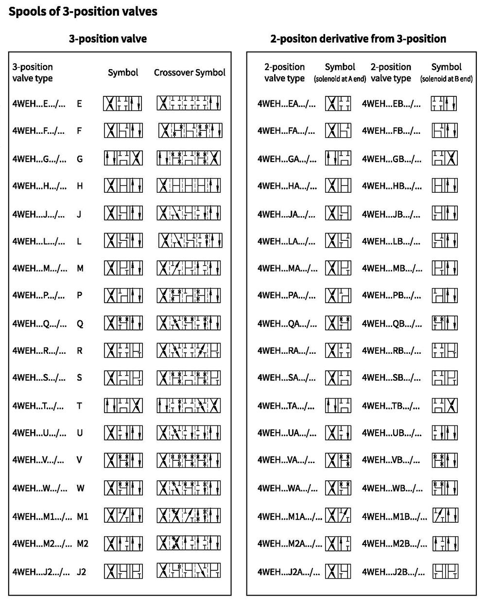
Symbols
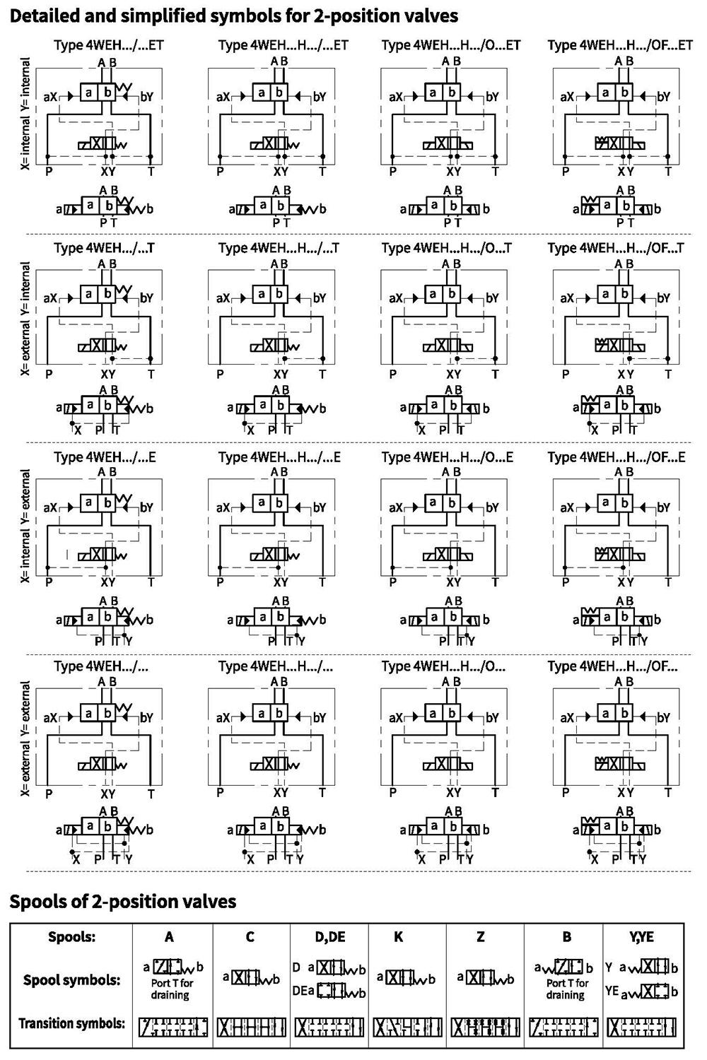
Technical details
1、Hydraulic section
1). WEH10 Type electro-hydraulic directional valve
| Maximum working pressure: bar P,A,B | Type WEH10 | ||||||||||
| 350 | |||||||||||
| Port T | With external pilot oil drain | bar | 315 | ||||||||
| With internal pilot oil drain | bar | DC210,AC160 | |||||||||
| Port Y | With external pilot oil drain | bar | DC210,AC160 | ||||||||
| Min.control pressure | With external pilot oil supply With internal pilot oil supply (not apply to C, Z,F,G,H,P,T,V) | bar | 3-position valve 10 | ||||||||
| Spring-return 2-position valve 10 | |||||||||||
| Hydraulic-return 2-position valve 7 | |||||||||||
| With internal pilot oil supply (apply to C,Z,F,G,H,P,T,V) | bar | 6.5 | |||||||||
| Max. control pressure bar | 250 | ||||||||||
| Hydraulic fluid | Mineral oil, phosphate oil | ||||||||||
| Temperature range of Hydraulic fluid ℃ | -30 to+80 (NBR seals) | ||||||||||
| -20 to+80 (FKM seals) | |||||||||||
| Viscosity range m㎡/s | 2.8 to 500 | ||||||||||
| Switching pilot oil volume cm3 | 3-position valve 2.04 2-position valve 4.08 | ||||||||||
| Switching times (=Valve switching time from the neutral position to the switched position) (AC and DC) | |||||||||||
| Control pressure bar | 70 | 140 | 210 | 250 | |||||||
| AC | DC | AC | DC | AC | DC | AC | DC | ||||
| -3- position valve ms | 30 | 65 | 25 | 60 | 20 | 55 | 15 | 50 | |||
| -2-position valve ms | 35 | 80 | 30 | 75 | 25 | 70 | 20 | 65 | |||
| Switching times (=Valve switching time from the neutra | l position to the switched position) | ||||||||||
| -3-position valve ms | 30 | ||||||||||
| -2-position valve ms | 35 | 40 | 30 | 35 | 25 | 30 | 20 | 25 | |||
| Flow of shortest switching time L/min | About 35 | ||||||||||
| Installation position | HC,HD, HK, HZ and HY of hydraulic return shall installed horizontally. The rest are arbitrary | ||||||||||
| Weight | Single solenoid valve | kg | 6.7 | ||||||||
| Double solenoid valve | 7.1 | ||||||||||
| Switching time regulator | 1.0 | ||||||||||
| Reducing valve | 0.5 | ||||||||||
Technical details
1、Hydraulic section
2). WEH16 Type electro-hydraulic directional valve
| Maximum working pressure: bar P,A,B | Type WEH16 | ||||||||||||
| 350 | |||||||||||||
| Port T | With external pilot oil drain bar | 250 | |||||||||||
| With internal pilot oil drain bar | DC210,AC160 | ||||||||||||
| Port Y | With external pilot oil drain bar | DC210,AC160 | |||||||||||
| Min.control pressure | With external pilot oil supply With internal pilot oil supply b | 3-position valve 14 | |||||||||||
| Spring-return 2-position valve 14 | |||||||||||||
| Hydraulic-return 2-position valve 14 | |||||||||||||
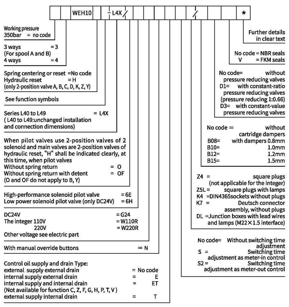
| ar With internal pilot oil supply | When applying prepressing or the flow is large correspondingly ,enginery of spool valve is 4.5 as C, Z,F,G,H,P,S,Tand V | ||||||||||||
| Max. control pressure bar | 250 | ||||||||||||
| Hydraulic fluid | Mineral oil, phosphate oil | ||||||||||||
| Temperature range of Hydraulic fluid ℃ | -30 to+80 (NBR seals) | ||||||||||||
| -20 to+80(FKM seals) | |||||||||||||
| Viscosity range m㎡/s | 2.8 to 500 | ||||||||||||
| cm3 Switching pilot oil volume cm3 | Spring-centering 3-position valve 5.72 | ||||||||||||
| 2-position valve 11.45 | |||||||||||||
| *Switching times (=Valve switching time from the neutral position to the switched position) (AC and DC) | |||||||||||||
| Control pressure bar | 50 | 150 | 250 | ||||||||||
| AC | DC | AC | DC | AC | DC | AC | DC | AC | DC | AC | DC | ||
| -Spring-centering 3-position valve ms | 35 | 65 | 30 | 60 | 30 | 58 | |||||||
| - 2-position valve ms | 45 | 65 | 35 | 55 | 30 | 50 | |||||||
| *Switching times (= Valve switching time from | the neutral position to the switched position) | ||||||||||||
| - Spring-centering 3-position valve ms | 30 | ||||||||||||
| - 2-position valve ms | 45 | 45 | 35 | 35 | 30 | 30 | |||||||
| Installation position | C,D,K,Z,Y Type hydraulic-return valves are installed horizontally, the rest can be installed arbitrarily | ||||||||||||
| Flow of shortest switching time L/min | About 35 | ||||||||||||
| Weight of the valve kg | About 9.5 | ||||||||||||
*Switching time refers to time from drawing of solenoid of pilot valve to full opening of main valve.
Technical details
1、Hydraulic section
3). WEH25 Type electro-hydraulic directional valve
| Maximum working pressure: bar P,A,B | Type WEH25 | ||||||||
| 350 | |||||||||
| Port T | With external pilot oil drain bar | 250 | |||||||
| With internal pilot oil drain bar | DC210,AC160 | ||||||||
| Port Y | With external pilot oil drain bar | DC210,AC160 | |||||||
| Min. control pressure | bar With external pilot oil supply bar With internal pilot oil supply bar | Spring-centering 3-position valve 13 | |||||||
| Spring-return 2-position valve 13 | |||||||||
| Hydraulic-return 2-position valve 8 | |||||||||
| With internal pilot oil supply bar | When applying prepressing or the flow s large correspondingly ,enginery of spool valve is 4.5 as C,Z,F,G,H,P,S,T and V | ||||||||
| Max. control pressure bar | 250 | ||||||||
| Hydraulic fluid | Mineral oil, phosphate oil | ||||||||
| Temperature range of Hydraulic fluid ℃ | -30 to+80 (NBR seals) | ||||||||
| -20 to+80 (FKM seals) | |||||||||
| Viscosity range m㎡/s | 2.8to 500 | ||||||||
| cm3 Switching pilot oil volume cm3 | Spring-centering 3-position valve 14.2 | ||||||||
| 2-position valve 28.4 | |||||||||
| * Switching times (=Valve switching time from the neutral position to the switched position) (AC and DC) | |||||||||
| Control pressure bar | 50 | 140 | 210 | 250 | |||||
| AC | DC | AC | DC | AC | DC | AC | DC | ||
| - Spring-centering 3-position valve ms | 50 | 85 | 40 | 75 | 35 | 70 | 30 | 65 | |
| - Spring-return 2-position valve ms | 120 | 160 | 100 | 130 | 85 | 120 | 70 | 105 | |
| Switching times (=Valve switching time from the n | eutral position to the switched position) | ||||||||
| - Spring-centering 3-position valve ms | 40 | ||||||||
| - Spring-return 2-position valve ms | 120 | 125 | 95 | 100 | 85 | 90 | 75 | 80 | |
| Installation position | C, D,K,Z,Y Type hydraulic-return valves are installed horizontally, the rest can be installed arbitrarily | ||||||||
| Flow of shortest switching time L/min | About 35 | ||||||||
| Weight of the valve Kg | About 18 | ||||||||
*Switching time refers to time from drawing of solenoid of pilot valve to full opening of main valve.11
Technical details
1、Hydraulic section
4). WEH32 Type electro-hydraulic directional valve
| Maximum working pressure: bar P,A,B | Type WEH32 | ||||||
| 350 | |||||||
| Port T | With external pilot oil drain bar | 250 | |||||
| With internal pilot oil drain bar | DC210,AC160 | ||||||
| Port Y | With external pilot oil drain bar | DC210,AC160 | |||||
| Min.control pressure | With external pilot oil supply bar With internal pilot oil supply | 3-position valve 8.5 | |||||
| Spring-return 2-position valve 10 | |||||||
| Hydraulic-return 2-position valve 5 | |||||||
| With internal pilot oil supply bar | When applying prepressing or the flow is large correspondingly ,enginery of spool valve is 4.5 as C,Z,F,G,H,P,S,T and V | ||||||
| Max.control pressure bar | 250 | ||||||
| Hydraulic fluid | Mineral oil,phosphate oil | ||||||
| Temperature range of Hydraulic fluid ℃ | -30 to+80 (NBR seals) | ||||||
| -20 to+80 (FKM seals) | |||||||
| Viscosity range m㎡/s | 2.8 to 500 | ||||||
| cm3 Switching pilot oil volume cm3 | Spring-centering 3-position valve 29.4 | ||||||
| 2-position valve 58.8 | |||||||
| * Switching times (=Valve switching time from the neutral position to the switched position) (AC and DC) | |||||||
| Control pressure bar | 50 | 150 | 250 | ||||
| AC | DC | AC | DC | AC | DC | ||
| -Spring-centering 3-position valve ms | 65 | 80 | 50 | 90 | 35 | 105 | |
| - Spring-return 2-position valve ms | 100 | 130 | 75 | 100 | 60 | 115 | |
| Switching times (= Valve switching time from the ne | utral position to the switched position) | ||||||
| - Spring-centering 3-position valve ms | (直流:50,交流:60) | ||||||
| - 2-position valve ms | 115 | 90 | 35 | 70 | 65 | 65 | |
| Installation position | C, D,K, Z,Y Type hydraulic-return valves are installed horizontally, the rest can be installed arbitrarily | ||||||
| Flow of shortest switching time L/min | About 50 | ||||||
| Weight of the valve kg | About 36 | ||||||
*Switching time refers to time from drawing of solenoid of pilot valve to full opening of main valve.
Technical details
2. Electrical data
| Type of voltage | Direct voltage | Alternating voltage | |
| Voltage (allowable fluctuation of ±10%) | 12,24,281,48,96, 110,205,220 | 110,127,220 | |
| Power(W) | High-performance solenoid valve 30 | Low-powered solenoid valve 16 | |
| Holding power (VA) | 50 | ||
| Starting power (VA) | 220 | ||
| Operating state | Continuous | ||
| Temperature range of environment (℃) | ~+50 | ||
| Temperature range of coil (℃) | ~+150 | ||
| Protection class to DIN40050 | IP65 | ||
1、Usually used for engineering machinery.
For other voltage, please consult the company.
Characteristic curves (Measured at θₒᵢ=40℃±5℃, using HLPS)
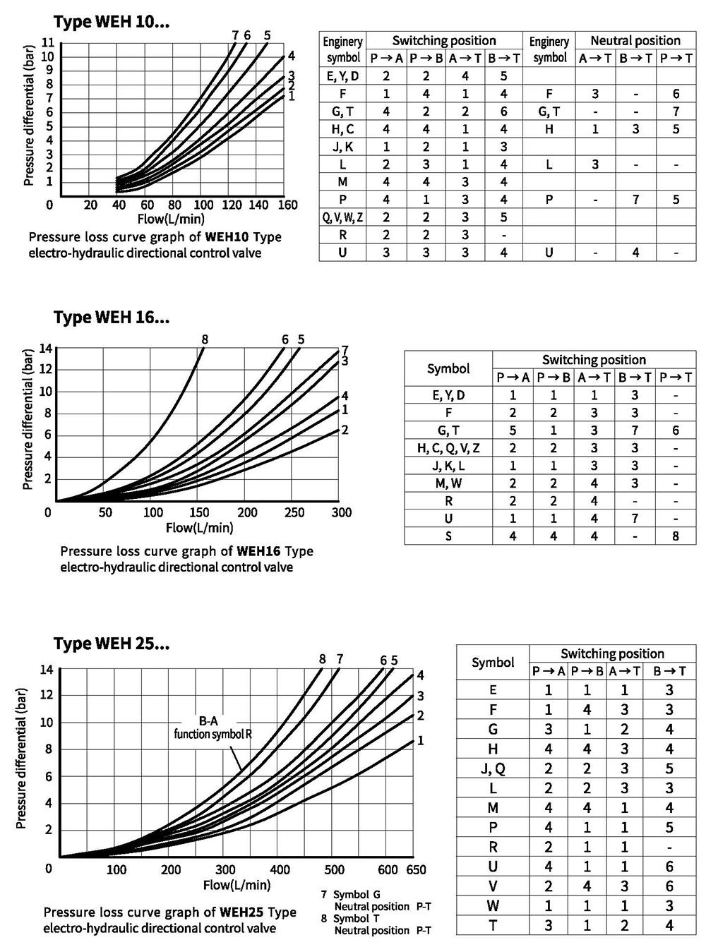
Characteristic curves (Measured at θₒᵢ=40℃±5℃, using HLPS)
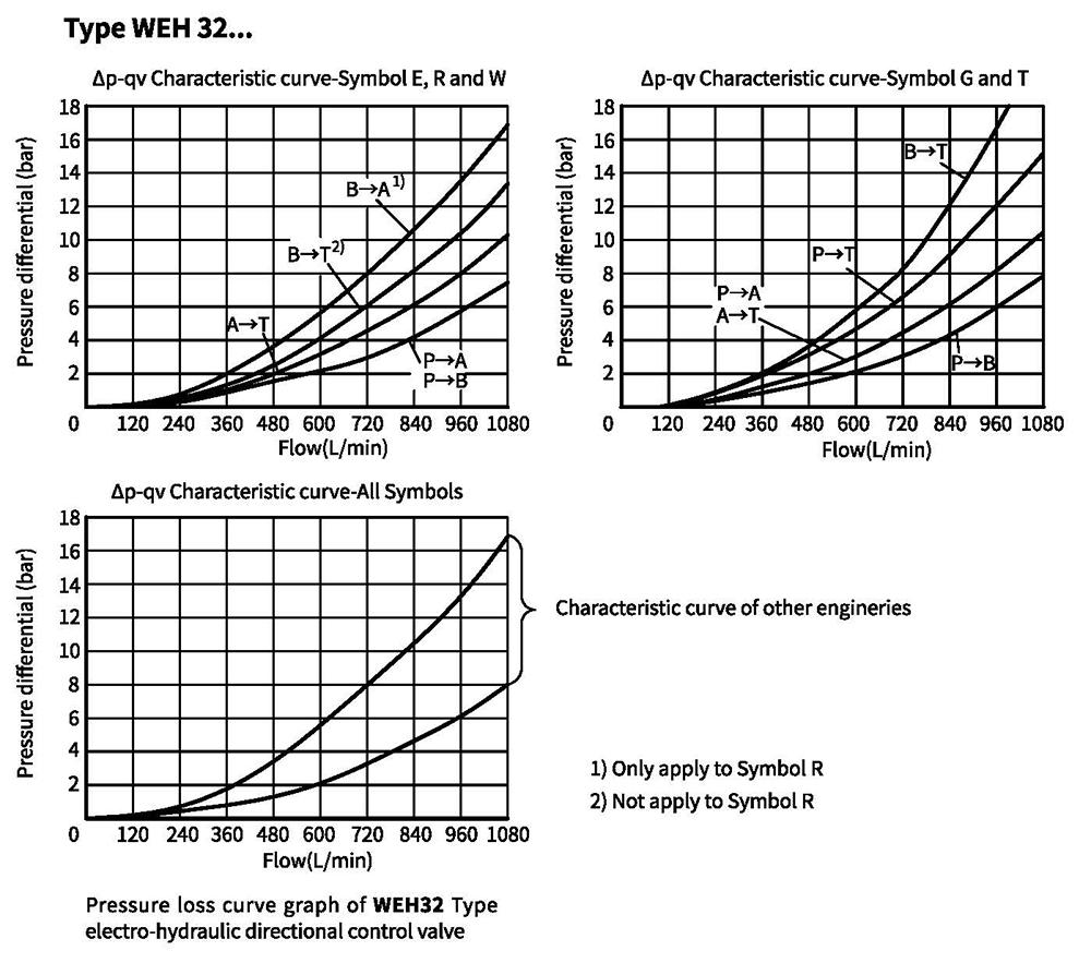
When valve is at the middle position,open area of all flow directions
| Size | Enginery | Open area(m㎡) | |||
| P→A | P→B | A→T | B→T | ||
| WEH10 | Q | - | - | 13 | 13 |
| V | 13 | 13 | 13 | 13 | |
| W | - | - | 2.4 | 2.4 | |
| WEH16 | Q | - | - | 32 | 32 |
| V | 32 | 32 | 32 | 32 | |
| W | - | - | 6 | 6 | |
| WEH25 | Q | - | - | 83 | 83 |
| V | 83 | 83 | 83 | 83 | |
| W | - | - | 14 | 14 | |
| WEH32 | Q | - | - | 78 | 78 |
| V | 73 | 73 | 84 | 84 | |
| W | - | - | 20 | 20 | |
Performance limit
The switching function of valves depends on filtration due to adhesive effects. To achieve the specified permissible flow values, we recommend full-flow filtration with 25 μm. The flow forces acting within the valves also have an influence on the flow performance. With 4-way directional valves, the specified flow data are therefore valid for normal applications with 2 directions of flow
(e.g. from P to A and simultaneous return flow from B to T) (see table).
If the fluid flows in only one direction, the permissible flow may be significantly lower in critical cases (e.g. use of a 4-way directional as 3-way directional valve with port A or B blocked).
Type: WEH10 electro-hydraulic directional control valve
| 3-position valve, spring centering | |||
| Flow(L/min) | Pressur stage(bar) | ||
| Symbol | 200 | 250 | 315 |
| E,J,L,M,Q,U,W,R,V | 160 | ||
| H | 160 | 150 | 120 |
| G,T | 160 | 140 | |
| F,P | 160 | 140 | 120 |
| 2-position valve whose main valve has a returning spring | | ||
| C,D,K,Z,Y | 160 | ||
| 2-position valve, main valve without spring | |||
| Flow(L/min) | Pressure stage(bar) | ||
| Symbol | 200 | 250 | 315 |
| HC HD HK HZ HY | 160 | ||
| HC.../O HD.../0 | 160 | ||
| HK.../O HZ.../O | |||
| HC.../OF... HD.../OF... HK.../OF... HZ.../OF... | 160 | ||
Type: WEH16 electro-hydraulic directional control valve
| Spring-centering 3-position valve | 2-position valve | ||||||||||
| Flow(L/min) | Pressure stage(bar) | Flow(L/min) | Pressure stage(bar) | ||||||||
| Symbol | 70 | 140 | 210 | 280 | 350 | Symbol | 70 | 140 | 210 | 280 | 350 |
| E,H,J,L,M, Q,U,W,R | 300 | 300 | 300 | 300 | 300 | C | 300 | 300 | 300 | 300 | 300 |
| D,Y | 300 | 270 | 260 | 250 | 230 | ||||||
| F,P | 300 | 250 | 180 | 170 | 150 | K | 300 | 250 | 240 | 230 | 210 |
| G,T | 300 | 300 | 240 | 210 | 190 | Z | 300 | 260 | 190 | 180 | 160 |
| S | 300 | 300 | 300 | 250 | 220 | Hydraulic-return 2 | -position valve | ||||
| V | 300 | 250 | 210 | 200 | 180 | HC,HD,HK,HZ,HY | 300 | 300 | 300 | 300 | 300 |
When control oil is supplied internally and pressure valve is equipped, the flow of spool valve's enginery of H, F, P, G,T, S, V, C and Z Types reaches 160L/min.
Performance limit
Type: WEH25 electro-hydraulic directional control valve
| 3-position valve of spring centering | 2-position valve | ||||||||||
| Flow(L/min) | Pressure stage(bar) | Flow(L/min) | Pressure stage(bar ) | ||||||||
| Symbol | 70 | 140 | 210 | 280 | 350 | Symbol | 70 | 140 | 210 | 280 | 350 |
| E,L,M | 650 | 650 | 650 | 650 | 650 | G,D,K,Z,Y | 650 | 650 | 650 | 650 | 650 |
| U,W,Q | Hydraulic-return 2-position valve ( main valve without spring) | ||||||||||
| G,T | 400 | 400 | 400 | 400 | 400 | HC HD HK HZ HY | 650 | 650 | 650 | 650 | 650 |
| F | 650 | 550 | 430 | 330 | 300 | ||||||
| H | 650 | 650 | 550 | 400 | 360 | HC.../O | 650 | 650 | 650 | 650 | 650 |
| J | 650 | 650 | 650 | 600 | 520 | HD.../O | |||||
| P | 650 | 550 | 430 | 330 | 300 | HK.../O | |||||
| V | 650 | 550 | 400 | 350 | 310 | HZ.../O | |||||
| R | 650 | 650 | 650 | 650 | 580 | HC.../OF... | 650 | 650 | 650 | 650 | 650 |
| G,T | 400 | 400 | 400 | 400 | 400 | HD.../OF... | |||||
| HK.../OF... | |||||||||||
| HZ.../OF... | |||||||||||
| When control oil is supplied internally and pressre valve is equipped, the flow of spool valve's enginery of G, Z, V,F,H,P, T Types reaches 180L/min. | |||||||||||
Type: WEH32 electro-hydraulic directional control valve
| 3-position valve of spring centering | 2-position valve | ||||||||||
| Flow(L/min) | Pressure stage(bar) | Flow(L/min) | Pressure stage(bar) | ||||||||
| Symbol | 70 | 140 | 210 | 280 | 350 | Symbol | 70 | 140 | 210 | 280 | 350 |
| E,J,L,M,R U,W,R | 1100 | 1040 | 860 | 750 | 680 | C,D,K,Z,Y | 1100 | 1040 | 860 | 750 | 680 |
| H,G | 1100 | 1000 | 680 | 500 | 450 | Hydraulic-return 2-position valve | |||||
| F,T,P | 820 | 630 | 510 | 450 | 400 | ||||||
| HC,HD,HK,HZ,HY | 1100 | 1040 | 860 | 750 | 680 | ||||||
| When control oil is supplied internally and pressure valve is equipped, the flow of spool valve's enginery of C, G, T, F,P,H, V and Z Types reaches 18OL/min. | |||||||||||
Pilot-operated solenoid valve
Use a four-way directional control valve with size of 6 to be a pilot valve. Spool valve is kept at the middle position or initial position by a spring and working position by the solenoid or positioner.
This valve applies wet DC or AC solenoid. Enginery of pilot-operated solenoid valve applied for main valve with different engineries are as the table below:
| Main valve | Pilot-operated solenoid valve |
| Spring-centering 3-position valve/ transformed 2-position valve | Use 4WE6J-6X/...3-position valve/ 4WE6JA... 4WE6JB... |
| Structure of 2-position main valve: Y.../...and HY.../... B.../...and HB.../... | Use 4WE6Y-6X/...2-position valve |
| 2-position valve: A,C,D,K and Z Type functions HA,HC,HD, HK, HZ Type valves | Use 2-position valve with D Type enginery Types of main valve's structure: spring return 4WE6D6X/.. No returning spring 4WE6D-6X/O... No returning spring, with a positioner 4WE6D-6X/OF... |
Unit dimensions
Unit dimensions of WEH 10 electro-hydraulic directional control valve
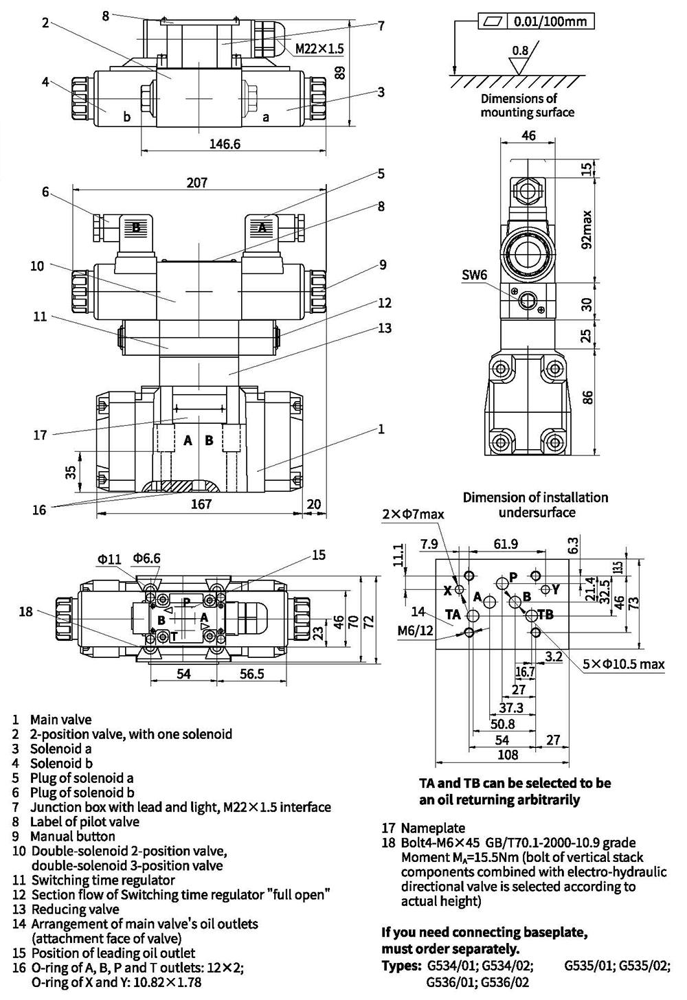
Unit dimensions
Unit dimensions of WEH 16 electro-hydraulic directional control valve
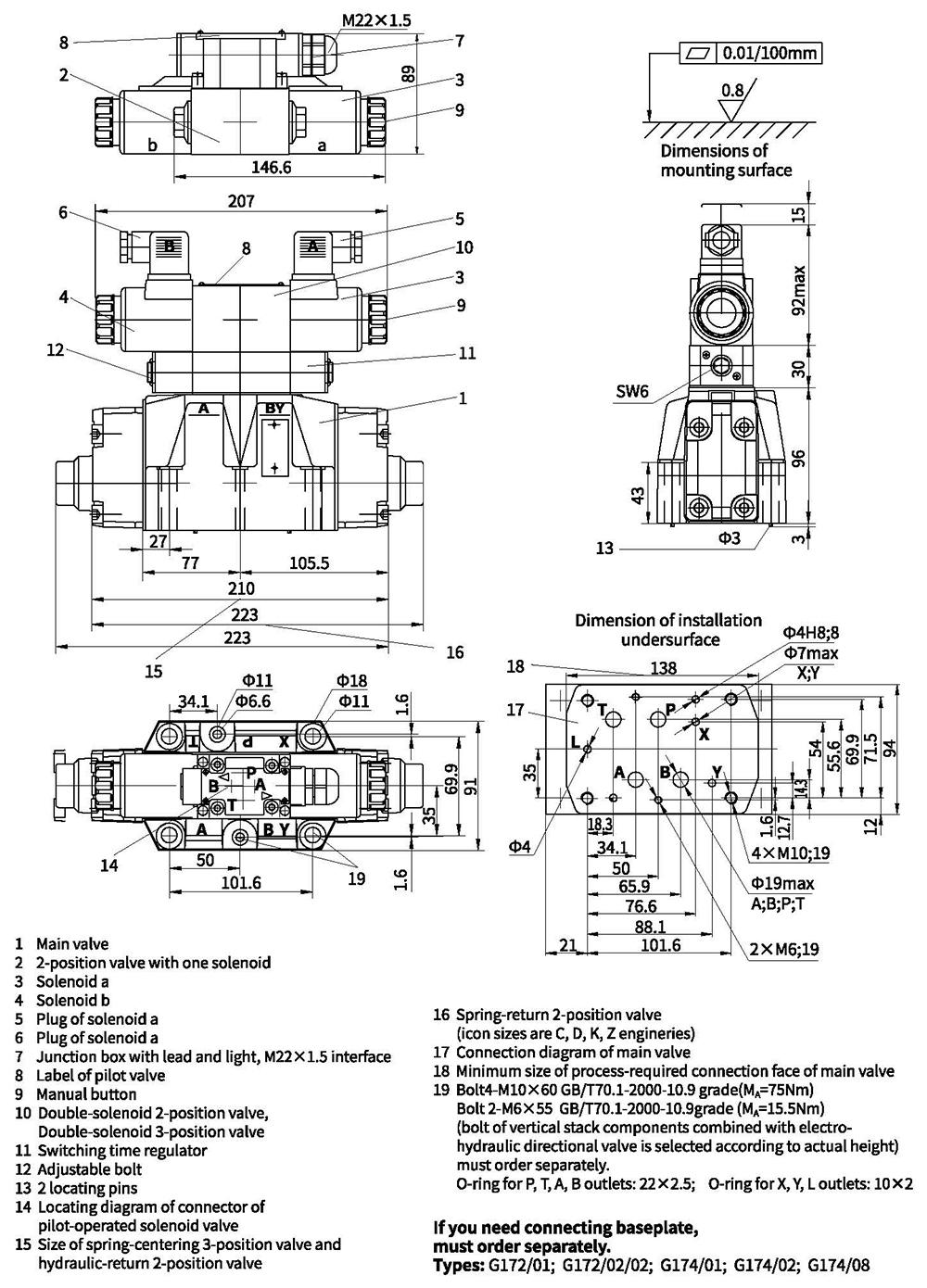
Unit dimensions
Unit dimensions of WEH 25 electro-hydraulic directional control valve
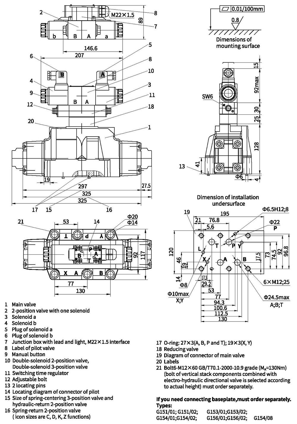
Unit dimensions
Unit dimensions of WEH 32 electro-hydraulic directional control valve