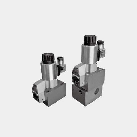
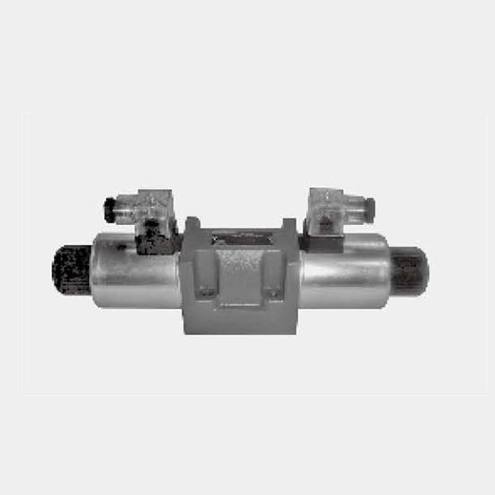
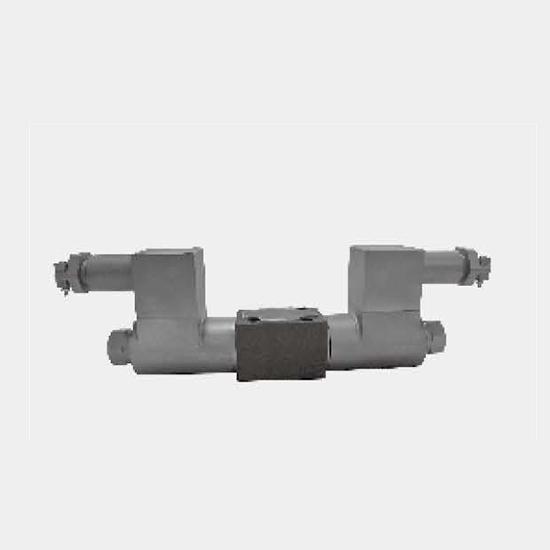
Function and configurationM‑SEW10 directional valve is a solenoid shut‑off directional poppet valve for control oil opening, stop and flow direction.Two‑position three‑way solenoid directional pop...
Product Detail
Function and configuration
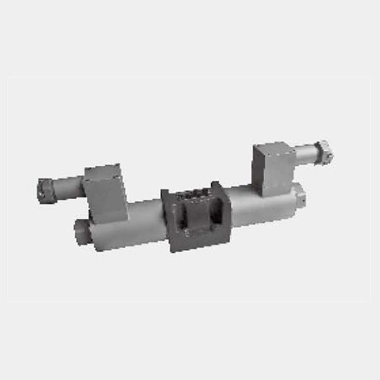
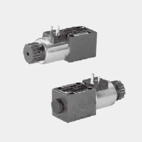
M‑SEW10 directional valve is a solenoid shut‑off directional poppet valve for control oil opening, stop and flow direction.
Two‑position three‑way solenoid directional poppet valve main consists of valve body (1), Solenoid (2), and valve element (3). Connect a superposition plate below the two‑position three‑way solenoid directional poppet valve to connect valve body (4), it becomes into two‑position four‑way direction poppet valve. Manual emergency button (5) can be used to operate the valve when the solenoid is not powered on.
M‑3SEW10 two‑position TEE solenoid directional poppet valve
1). Initial position: when the solenoid is not energized, pretention of spring (6) keeps valve element (3) on valve seat (7) on the left, so that oil port P is connected to A and oil port T is closed.
2). Switching position: after the solenoid is energized, through angular lever (9) and ball (10), the force of Solenoid (2) acts on push rod (11) of the two‑side seal, thus to push valve element (3) and maintain it on right valve seat (8), causing oil port P closed and oil port A connected to port T. Since push rod (11) and valve element (3), acted by the inlet pressure, is in a balance state of axial hydraulic pressure, therefore, the valve can be used when pressure is up to 420bar.
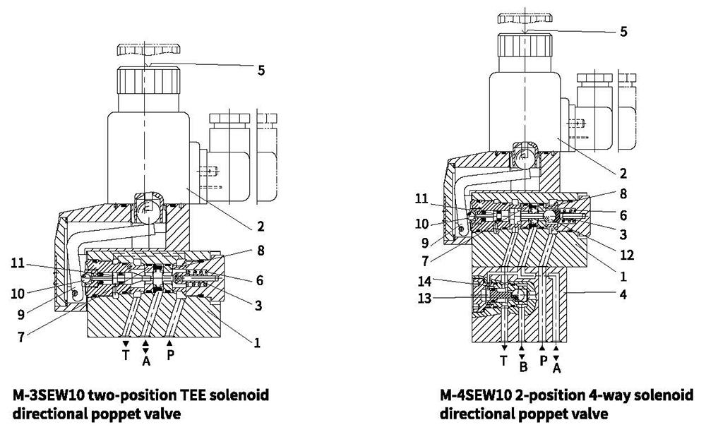
M‑4SEW10 2‑position 4‑way solenoid directional poppet valve
1). Initial position:
when the Solenoid is not energized, pretention of spring (6) keeps valve element (12) on valve seat (8) on the right, oil port P is closed and port A connected to T; pressure oil supplied from oil port P push steel ball (13) to valve seat (14), upon which oil port P is connected to B and A connected to T; control oil line is connected from oil port A acts on the larger area of control piston (12), which can be used for unloading to oil tank.
2). Switching position:
after the Solenoid is energized, oil port P is connected to A; pressure oil from the pump goes through the control oil line connected from port A and acts on the larger area of control piston (12); steel ball (13) is pushed to the other side of valve seat (14), thus oil port P is connected to A and B connected to T.
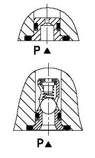
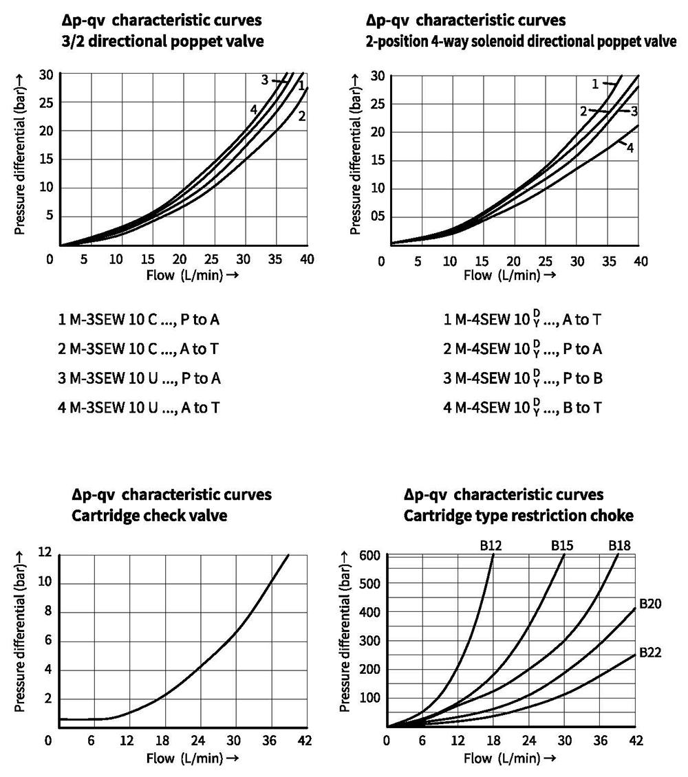
Cartridge restriction choke (model M‑.SEW10.L1X/…/B…)
To restrict flow through the valve, a restriction choke can be installed.
Restriction choke is installed on port P.
Cartridge type one‑way valve (model M‑.SEW10.L1X/…/P)
Cartridge type one‑way valve allows oil flow in from port P and
it is closed for reverse flowing.
One‑way valve installed on port P.
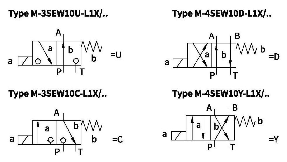
Spool symbols
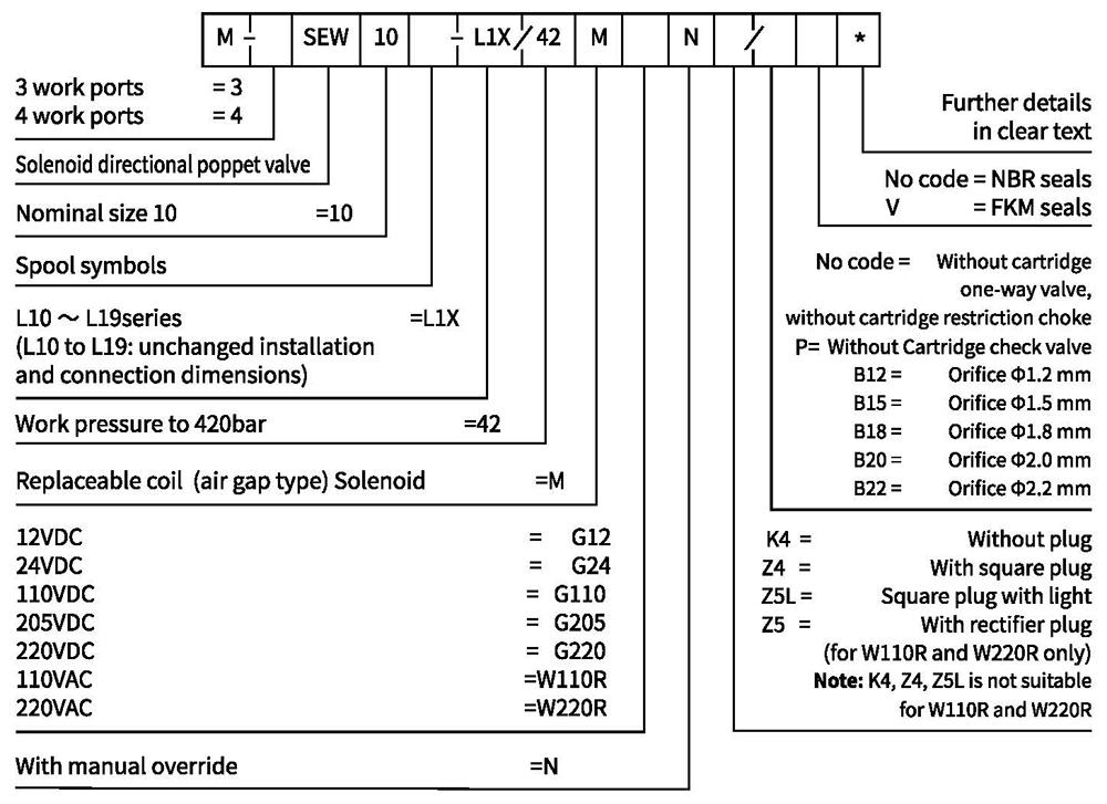
Ordering code
Technical data
| Installation position | Optional | ||
| Environment temperature ℃ | -30 to+50 (NBR seal) | ||
| -20 to+50 (FKM seal) | |||
| Weight | Two tee Solenoidic directional valve | 2.0 | |
| Two four-way Solenoidic directional Kg valve | 3.5 | ||
| Max operation pressure | Port P,A, B bar Port T | 420 | |
| 100 | |||
| Max flow L/min | 40 | ||
| Fluid | Mineral oil suitable for NBR and FKM seal | ||
| Phosphate ester for FKM seal | |||
| Fluid temperature range ℃ | -30 to +50 (NBR seal) | ||
| -20 to +50 (FKM seal) | |||
| Viscosity range m㎡/s | 2.8 to 500 | ||
| Degree of contamination | Maximum permissible degree of fluid contamination: Class 9. NAS 1638 or 20/18/15,ISO4406 | ||
Electrical data
| Voltage type | DC | AC | |||||||||||||
| Available voltage V | 12,24,110,205,220 | 110,220 (Only by Z5 rectifier plug) | |||||||||||||
| Allowed voltage (deviation) % | +10~-15 | ||||||||||||||
| Required power W | 30 | ||||||||||||||
| Continuous power-on time % | 100 | ||||||||||||||
| Switching time in compliance with ISO 6403 | |||||||||||||||
| Pressure bar | Flow L/min | DC | AC50HZ | ||||||||||||
| On/ms (without oil tank pressure) | Off/ms | On/ms (without oil tank pressure) | Off/ms | ||||||||||||
| U | C | D | Y | U,C | D,Y | U | C | D | Y | U | C | D | Y | ||
| 140 | 40 | 20 | 40 | 20 | 40 | 12 | 17 | 20 | 40 | 20 | 40 | 60 | 45 | 40 | 50 |
| 280 | 40 | 25 | 45 | 20 | 45 | 12 | 17 | 20 | 45 | 25 | 45 | 60 | 45 | 45 | 55 |
| 320 | 40 | 25 | 45 | 20 | 45 | 12 | 17 | 25 | 45 | 25 | 45 | 60 | 45 | 45 | 55 |
| 420 | 40 | 30 | 45 | 20 | 50 | 12 | 17 | 25 | 45 | 25 | 50 | 60 | 45 | 45 | 55 |
| Switching frequency Time/h | Up to 15000 | ||||||||||||||
| IP rating as per DIN 40050 | IP65 | ||||||||||||||
| Max coil temperature ℃ | +150 | ||||||||||||||
Note: for electrical connection, protective wire (PE 1/) shall be earthed as required.
Characteristic curves (Measured at oil=40°C +5°C, using HLP46)
Unit dimensions
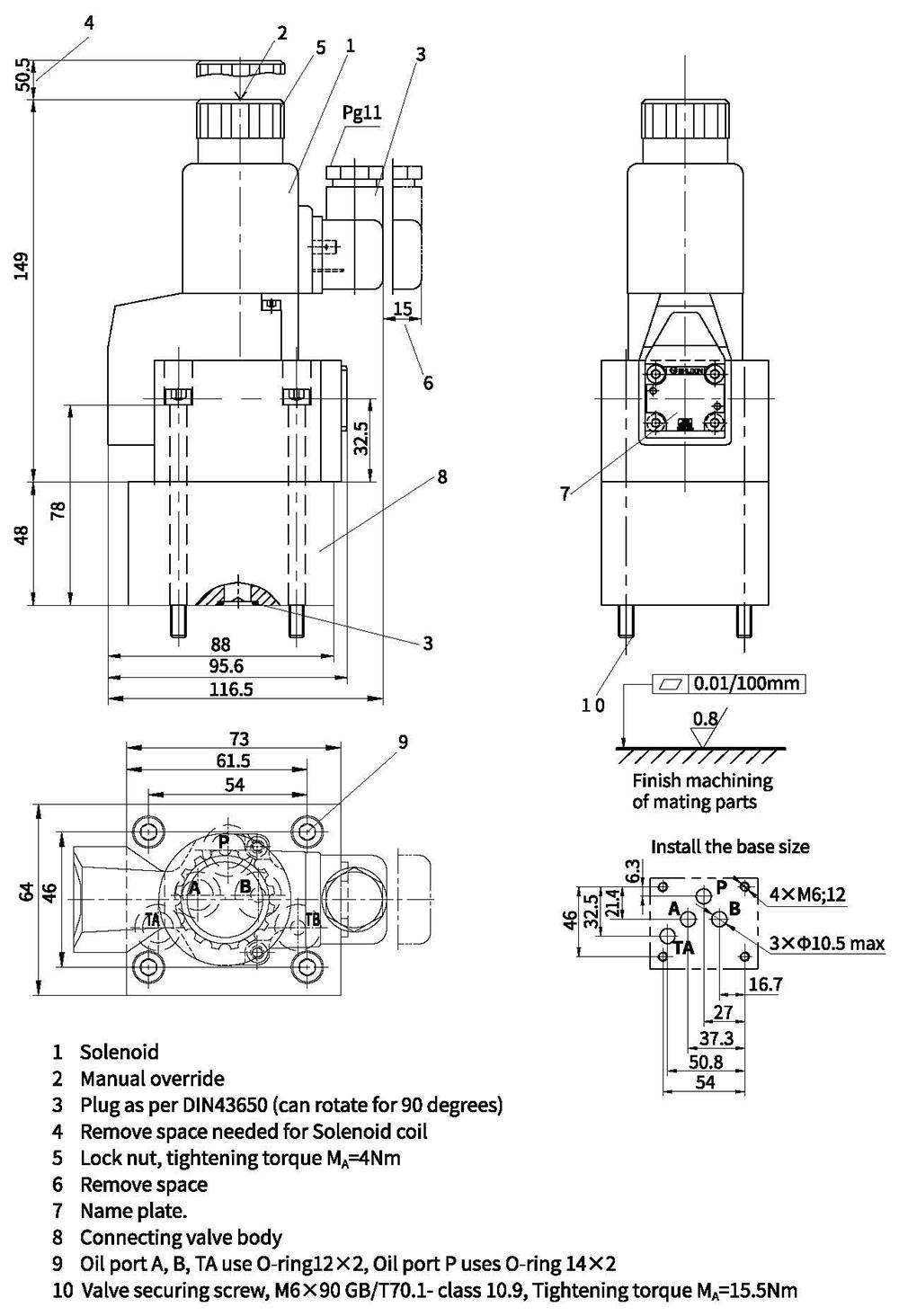
·2-position 3-way solenoid directional poppet valve
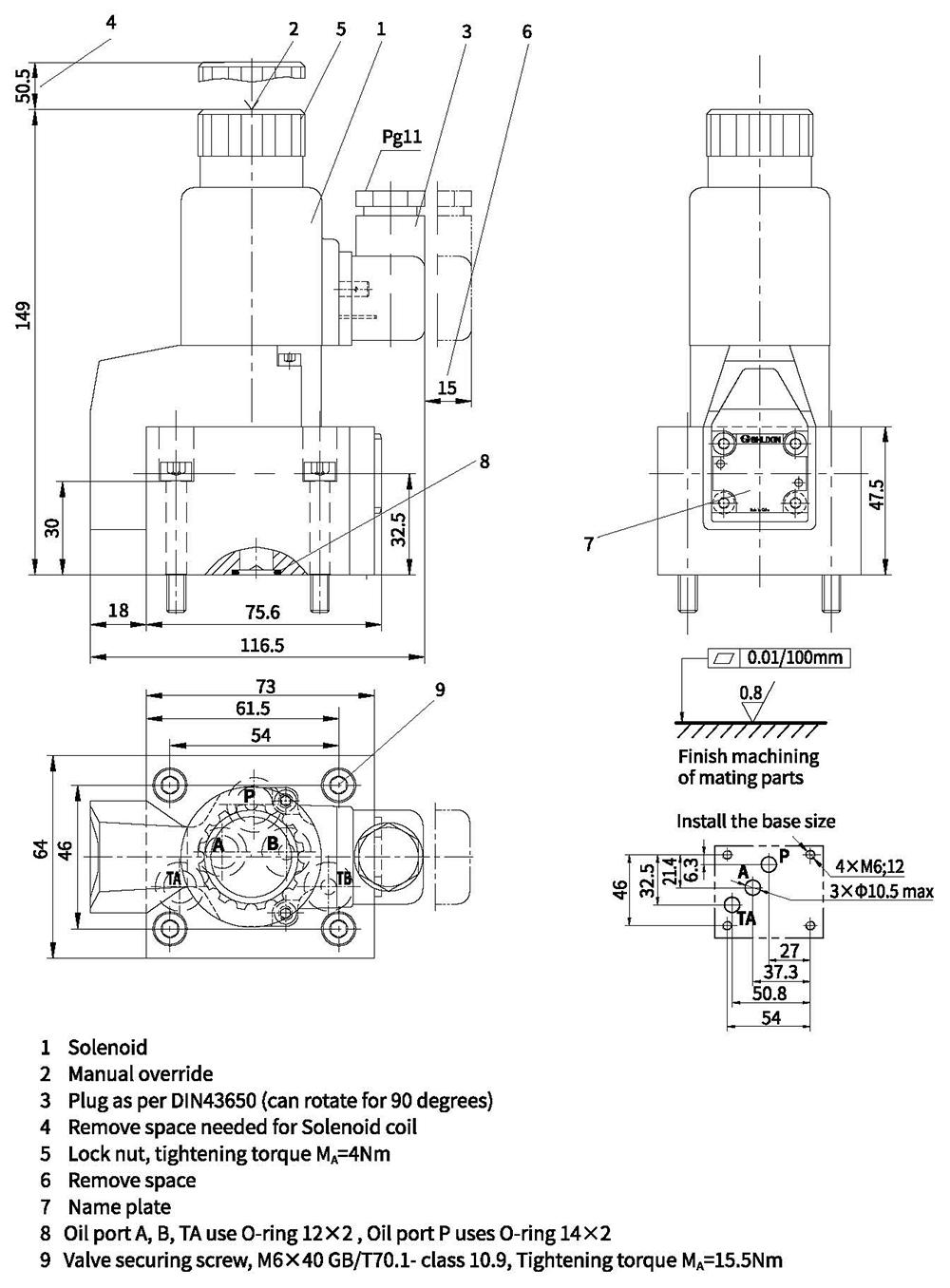
Unit dimensions
.2-position 4-way solenoid directional poppet valve