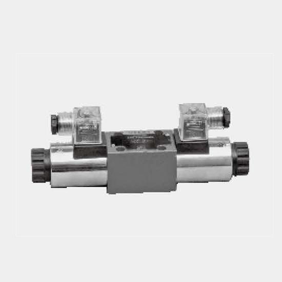
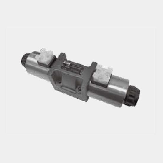
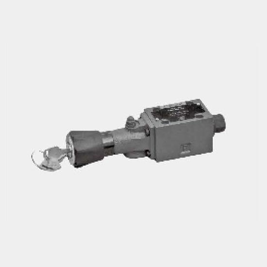
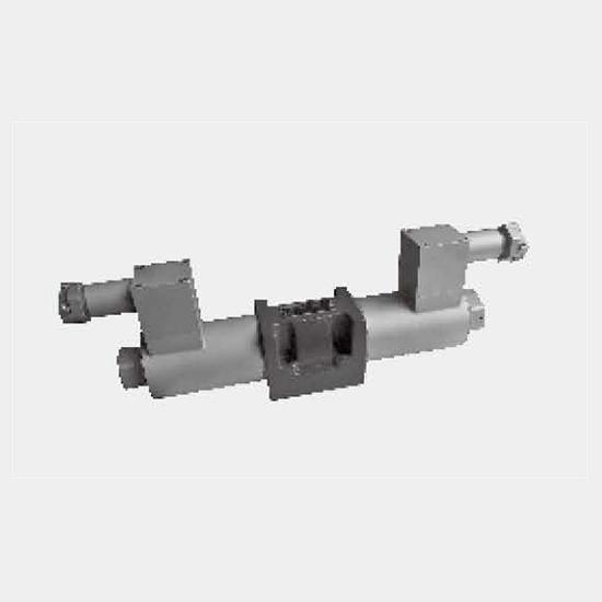
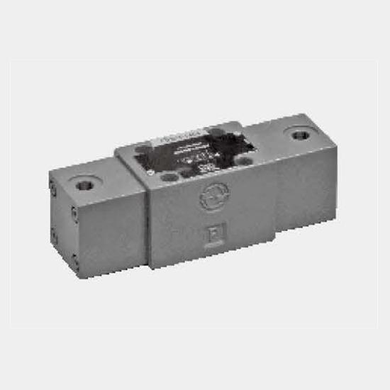
Function and configurationType WE valves are solenoid operated directional spool valves. They control the start, stop and direction of flow.The directional control valves consist of housing (1), one o...
Product Detail
Function and configuration
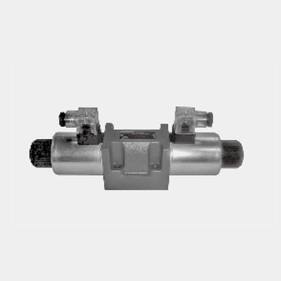
Type WE valves are solenoid operated directional spool valves. They control the start, stop and direction of flow.
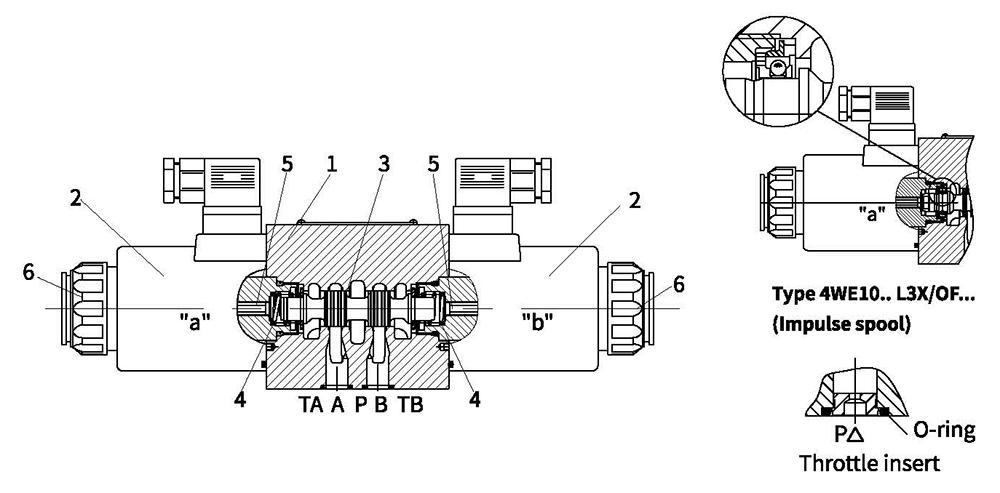
The directional control valves consist of housing (1), one or two solenoids (2), the control spool (3), and one or two return springs (4).
In the de‑energized condition the control spool (3) is held in the neutral or initial position by means of return springs (4) (except for pulse spools). The control spool (3) is actuated via wet pin solenoids (2).
To ensure proper operation, care must be taken that the pressure chamber of the solenoid is filled with oil.
The control spool(3) is moved to the expected position by solenoid(2) and pushing rod(5), and this gives free‑flow from P to A and B to T or P to B and A to T.
When solenoid (2) is de‑energized, the control spool (3) is returned to its neutral position by means of the return springs (4).
The solenoids may also control the control spool (3) by an optional override button(6) under the de‑energized condition.
For application in voltage pulsation, solenoids with large scope voltage are recommended. For application in high protective grade, waterproof plug should be used.
Type 4WE10.. L3X/O...
(Only for symbols A, C and D)
This Type is a 2‑position directional valve with 2 solenoids without detents. The spool position, when the solenoids are de‑energised, is not defined..
Type 4WE10.. L3X/OF...
(Impulse spool, only for symbols A, C and D)
This Type is a 2‑position directional valve with 2 solenoids and detents. Hence, when the solenoids are de‑energized, the spool is held in the detented position then the solenoids do not need to be continuously energised.
Throttle insert (type 4WE10...L3X/.../B..)
The use of a throttle insert is required if, due to the operating conditions, flows can occur during the switching process which are larger than the performance limits of the valve allow.
The orifice is to be inserted into the P channel of the directional valve.
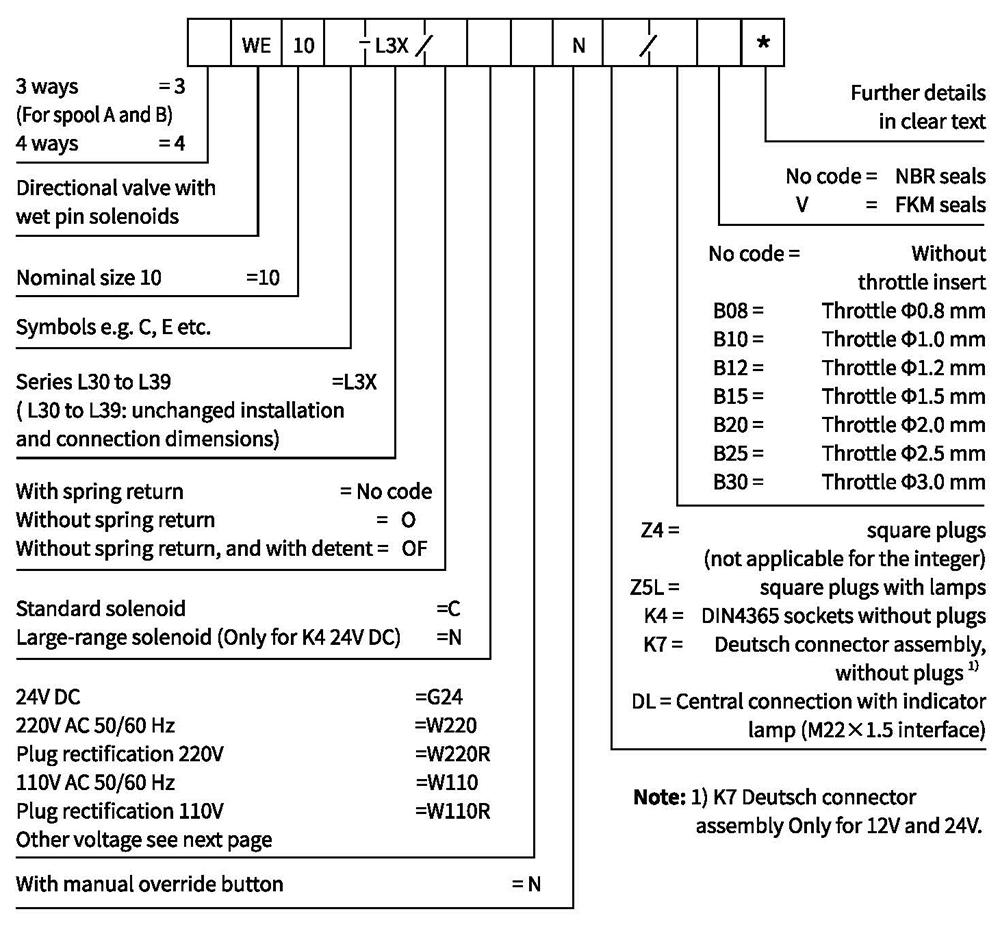
Ordering code
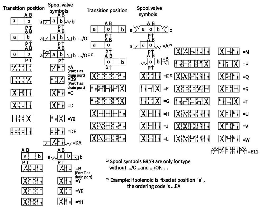
Symbols
Characteristic curves (Measured at θₒᵢₗ=40℃±5℃, using HLP)
| Spool symbol | Flow direction | |||
| PtoA | Pto B | A to T | B to T | |
| A,B | 3 | 3 | - | - |
| C | 3 | 3 | 4 | 5 |
| D,Y | 5 | 5 | 6 | 6 |
| E | 1 | 1 | 4 | 4 |
| F | 2 | 3 | 7 | 4 |
| G | 3 | 3 | 6 | 7 |
| H | 1 | 1 | 6 | 7 |
| J | 1 | 1 | 3 | 3 |
| L | 2 | 2 | 3 | 5 |
| M | 1 | 1 | 4 | 5 |
| P | 4 | 2 | 5 | 7 |
| Q | 1 | 2 | 1 | 3 |
| R | 3 | 6 | 4 | - |
| T | 3 | 3 | 6 | 7 |
| U,V | 2 | 2 | 3 | 3 |
| W | 2 | 2 | 4 | 5 |
Technicaldata
| Fixing position | Optional | ||
| Environment temperature range ℃ | -30 to +50 (NBR seal) | ||
| -20 to +50 (FKM seal) | |||
| Weight | Independently wiring | central monitoring station | |
| Single solenoid kg | 4.3(DC), 3.5(AC) | 4.4(DC),3.6(AC) | |
| Double solenoids kg | 5.9(DC),4.3(AC) | 6.0 (DC),4.4(AC) | |
| Max.operating pressure | Port A,B,P bar | 315 | |
| Port T bar | 210 (DC),160 (AC), when the operating pressure exceedsthe permission value, spool symbol A and B must make the port T for draining. | ||
| Max. flow-rate L/min | 120 | ||
| Flow cross section (switching neutral position) | Version V m㎡ | 11(A/B to T), 10.3(PtoA/B) | |
| Version W m㎡ | 2.5(A/B to T) | ||
| Version Q m㎡ | 5.5(A/B to T) | ||
| Fluid | Mineral oil suitable for NBR and FKM seal | ||
| Phosphate ester for FKM seal | |||
| Fluid temperature range ℃ | -30 to +80 (NBR seal) | ||
| -20 to +80 (FKM seal) | |||
| Viscosity range m㎡/s | 2.8 to 500 | ||
| Degree of contamination | Maximum permissible degree of fluid contamination: Class 9. NAS 1638 or 20/18/15,ISO4406 | ||
Electric data
| Type of voltage | DC | AC | |
| Available voltage V | 12,24,28,48,96,110,205,220 | 110,127,220 | |
| Voltage tolerance (nominal voltage) % | Standard solenoid:+10~-15 large-scope solenoid:+20~-30 | ||
| Power consumption W | Standard solenoid:35 large-scope solenoid: 42 | ||
| Holding power VA | - | 50 | |
| Making capacity VA | - | 550 | |
| Duty | Continuous working | ||
| Switching time to ISO 6403 | ON ms | 45 to 60 | 15 to 25 |
| OFF ms | 20 to 30 | 20 to 30 | |
| Switched frequency times/h | to 15000 | to 7200 | |
| Type of protection to DIN 40050 | IP65(Z4,Z5L plug), IP67 (K7 Deu | tsch) | |
| Max. coils temperature ℃ | +150 | +180 | |
Caution: When connecting wires, properly connect the PE conductor (PE ⊥).
( For other type voltage please consult us. )
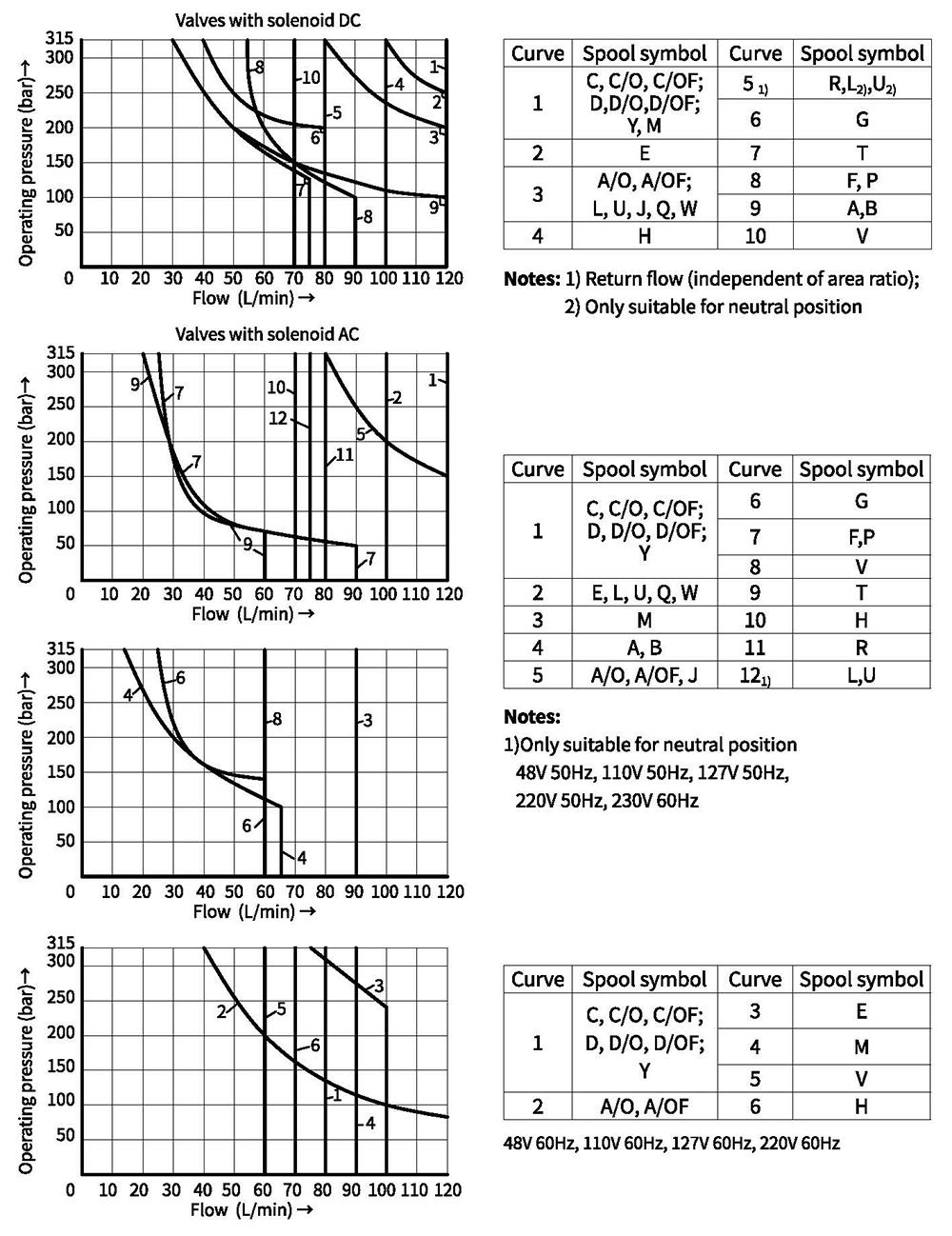
Performance limits (Measured at θₒᵢₗ=40℃±5℃, using HLP)
The performance limits shown are valid when the valve is used with two directions of flow (e.g. from P to A with simultaneous return flow from B to T).
Due to the flow forces occuring within the valves, the permissible switching performance limits can be significantly lower with only one direction of flow (e.g. from P to A and port B blocked)! (For these applications, please consult us.)
The performance limit was determined with the solenoids at their operating temperature, 15% under voltage and with no pre‑loading of the tank.
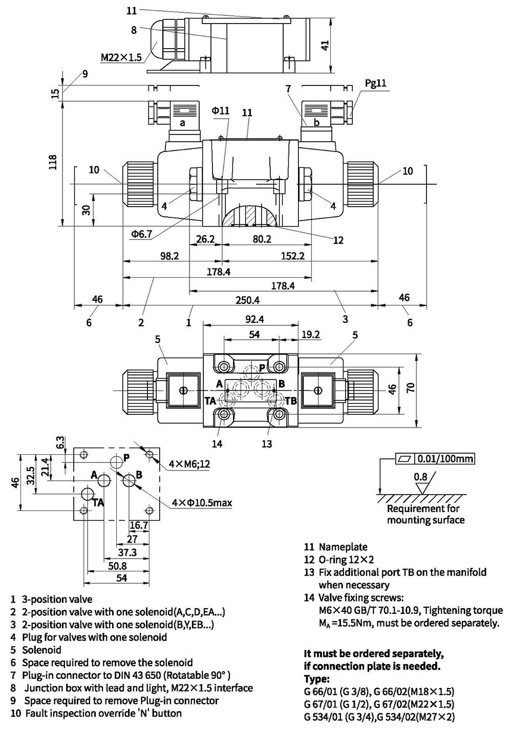
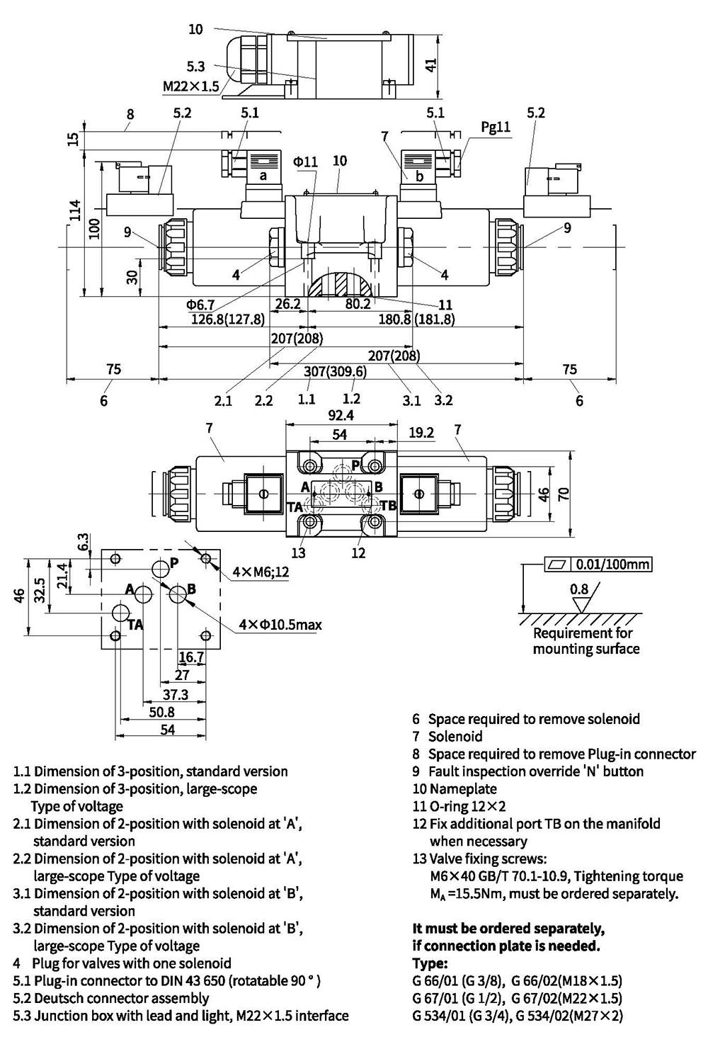
Unit dimensions
Valve with DC or rectification AC solenoid
Unit dimensions
Valve with AC solenoid