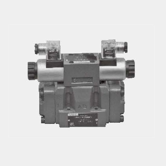
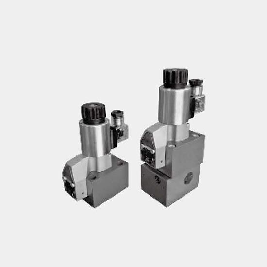
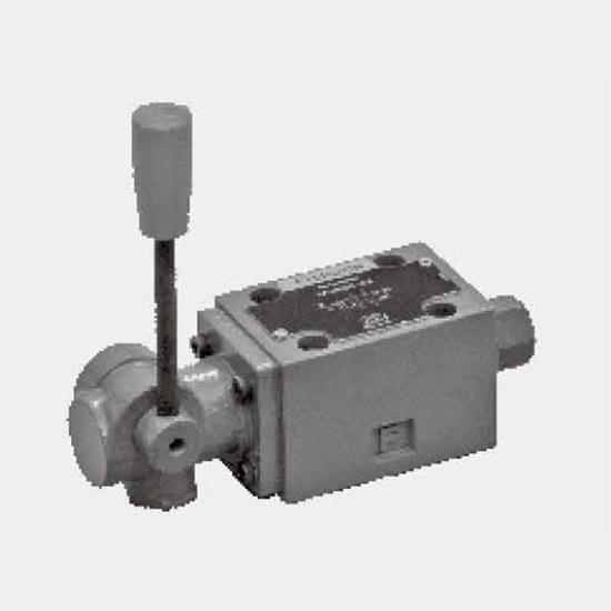
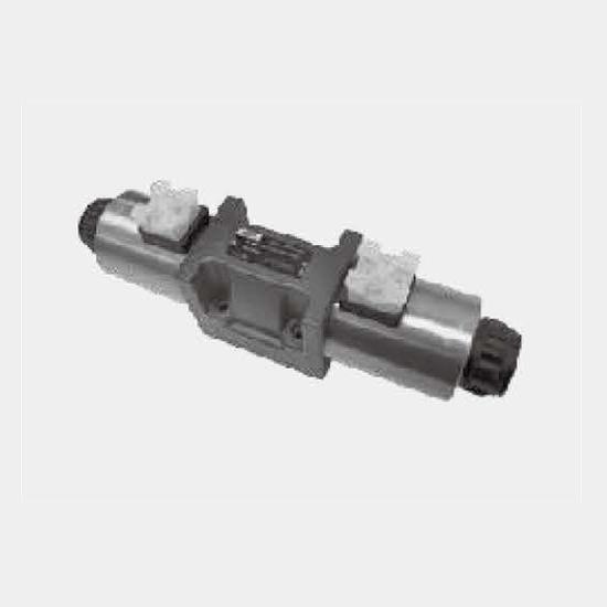
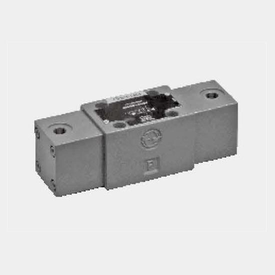
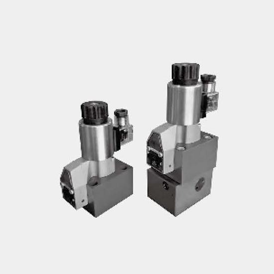
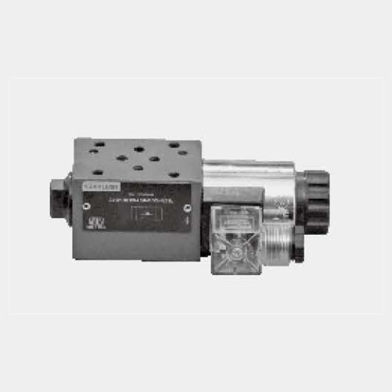
Function and configuration·Type M‑3SED10 3/2 directional poppet valveDirectional valves of the type SED are direct operated directional poppet valves with solenoid actuation. They control the start,...
Product Detail
Function and configuration
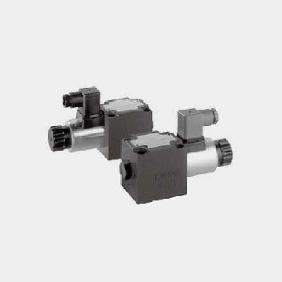
·Type M‑3SED10 3/2 directional poppet valve
Directional valves of the type SED are direct operated directional poppet valves with solenoid actuation. They control the start, stop and direction of flow.
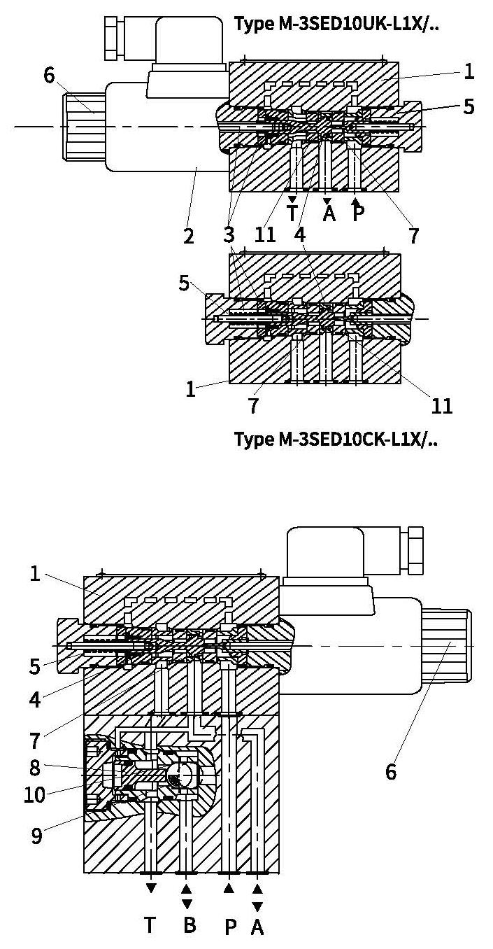
The directional poppet valves consist of housing(1), the solenoid(2), the valve seat(7) and (11) and the control spool(4).
The manual override(6) allows for the switching of the valve without solenoid energization.
General principle (3/2 directional poppet valve):
The initial position of the valve (normally open "UK" or normally closed "CK") is determined by the arrangement of the spring(5). The chamber(3) behind the control spool(4) is connected to port P and sealed against port T. Thus, the valve is pressure‑compensated in relation to the actuating forces (solenoid and spring).
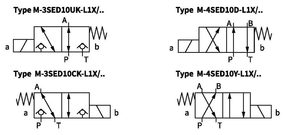
By means of the control spool(4), the port P, A and T can be loaded with maximum operating pressure (350bar) and the flow can be directed in both directions (see symbols).
In the initial position, the control spool(4) is pressed onto the seat(11) by the spring(5), in spool position,it is pressed onto the seat(7) by the solenoid(2). The flow is blocked.
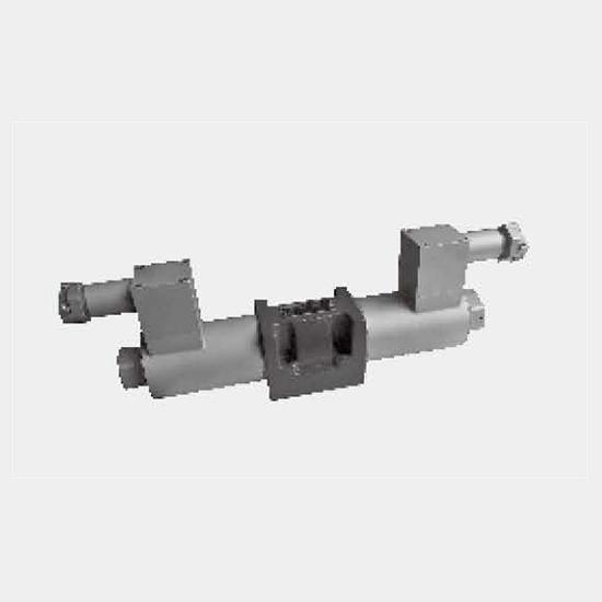
·Type M‑4SED10 4/2 directional poppet valve
With a sandwith plate,the Plus‑1plate, under the 3/2 directional poppet valves, the function of a 4/2 directional poppet valve is achieved.
1). Initial position:
the main valve is not actuated. The spring(5)holds the control spool(4)on the seat(11). Port P is blocked and A is connected to T. Apart from that, one control line is connected from A to the large area of the control spool(8), which is thus unloaded to the tank.The pressure applied via P now pushes the ball(9) onto the seat(10). Now, P is connected to B, and A to T.
2). Transition position:
When the main valve is actuated, the control spool(4) is shifted against the spring(5) and pressed onto the seat(7). During this, port T is blocked, P, A, and B are briefly connected to each other.
3). Spool position:
P is connected to A.As the pump pressure acts via A on the large area of the control spool(8), the ball(9) is pressed onto the seat(12). Thus, B is connected to T, and P to A. The ball(9) in the Plus‑1 plate has a "positive spool overlap".
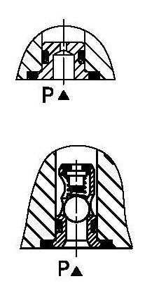
Throttle insert:
The use of a throttle insert is required, if, due to the operating conditions, flows are to be expected during the switching procedure, which are higher than the started maximum performance limits of the valve.
The throttle is inserted into port P of the valve.
Cartridge check valve:
The cartridge check valve allows free flow from P to A and provides leak‑free closed from A to P.
The cartridge check valve is inserted into port P of the valve.
Spool symbols
 11
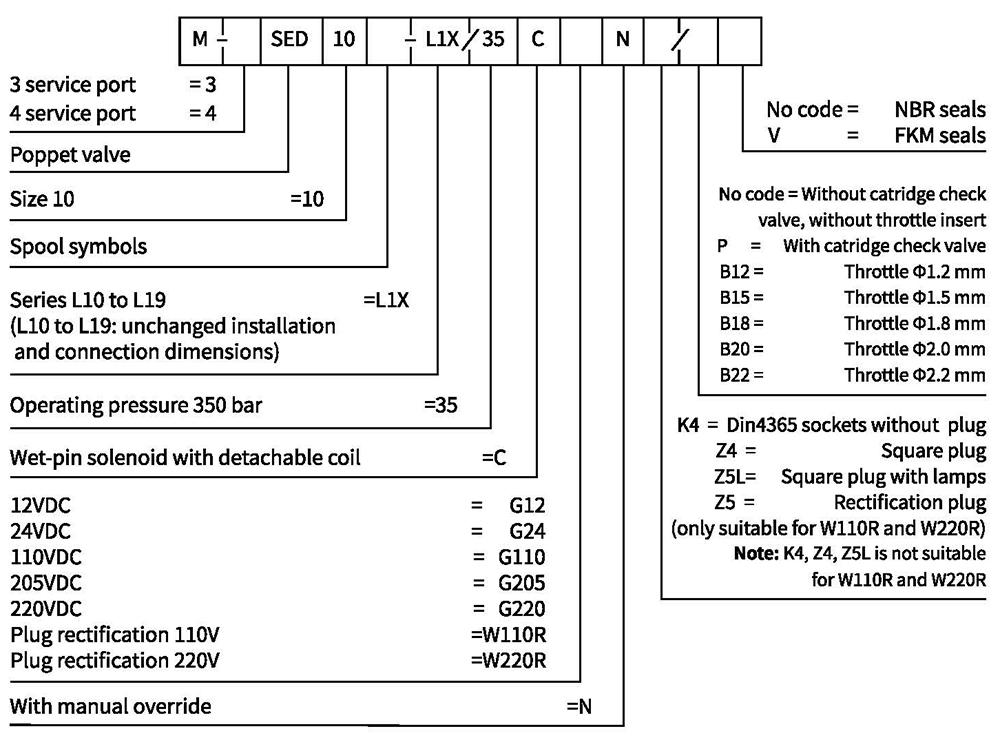
Ordering code
Technical data
| Installation position | Optional | |
| Environment temperature ℃ | -30 to +50 (NBR seal) | |
| -20 to +50 (FKM seal) | ||
| Weight | Two tee Solenoidic directional valve Kg | 2.6 |
| Two four-way Solenoidic directional valve Kg | 3.9 | |
| Max operation pressure bar | 350 | |
| Max flow L/min | 40 | |
| Hydraulic fluid | Mineral oil suitable for NBR and FKM seal | |
| Phosphate ester for FKM seal | ||
| Fluid temperature range ℃ | -30 to +80 (NBR seal) | |
| -20 to +80(FKM seal) | ||
| Viscosity range m㎡/s | 2.8 to 500 | |
| Degree of contamination | Maximum permissible degree of fluid contamination: Class 9. NAS 1638 or 20/18/15, ISO4406 | |
Electrical data
| Voltage type | DC | AC+rectifier | |||||||||||
| Voltage version V | 12,24,110,205,220 | 110,220 (only possible via Z5 rectifier) | |||||||||||
| Permissible voltage(deviation) % | +10~-15 | ||||||||||||
| Input power W | 30 | ||||||||||||
| Continuous power-on time | Continuous | ||||||||||||
| Switching time to ISO 6403 | |||||||||||||
| Pressure bar | Flow L/min | DC solenoid | AC +rectifier | ||||||||||
| On/ms (without oil tank pressure) | Off/ms | On/ms (without oil tank pressure) | Off/ms | ||||||||||
| UK | CK | D | Y | UK,CK | D,Y | UK | CK | D | Y | UK,CK | D,Y | ||
| 70 | 40 | 40 | 30 | 40 | 35 | 10 | 10 | 35 | 30 | 40 | 35 | 40 | 40 |
| 140 | 40 | 40 | 30 | 40 | 35 | 10 | 10 | 40 | 30 | 40 | 35 | 40 | 40 |
| 210 | 40 | 45 | 35 | 45 | 35 | 10 | 10 | 45 | 35 | 45 | 35 | 40 | 40 |
| 280 | 40 | 45 | 35 | 45 | 35 | 10 | 10 | 45 | 35 | 45 | 35 | 40 | 40 |
| 315 | 40 | 50 | 35 | 50 | 35 | 10 | 10 | 50 | 40 | 50 | 35 | 40 | 40 |
| 350 | 40 | 50 | 45 | 50 | 45 | 10 | 10 | 50 | 45 | 50 | 45 | 40 | 40 |
| Note: The switching types relate to a flow of P to A and A to T. With reversed flows deviations are possible. | |||||||||||||
| Switching frequency Cycles/h | to 15000 | ||||||||||||
| IP rating as per DIN 40050 | IP65 | ||||||||||||
| Max coil temperature ℃ | +150 | ||||||||||||
Note: The switching types relate to a flow of P to A and A to T. With reversed flows deviations are possible.
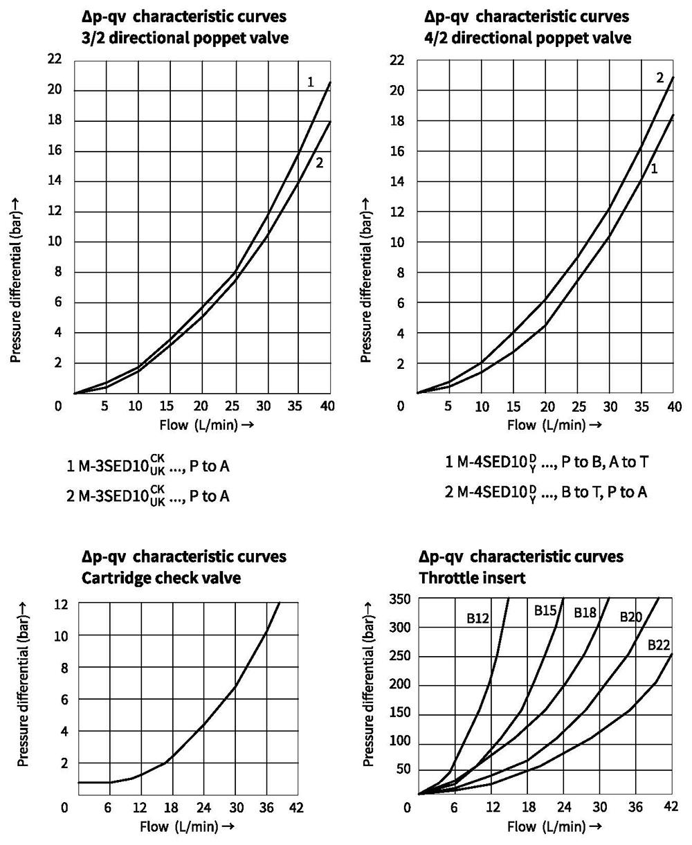
Characteristic curves (Measured at oil=40°C +5°C,using HLP46)
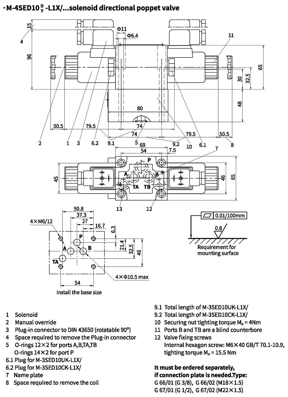
Unit dimensions
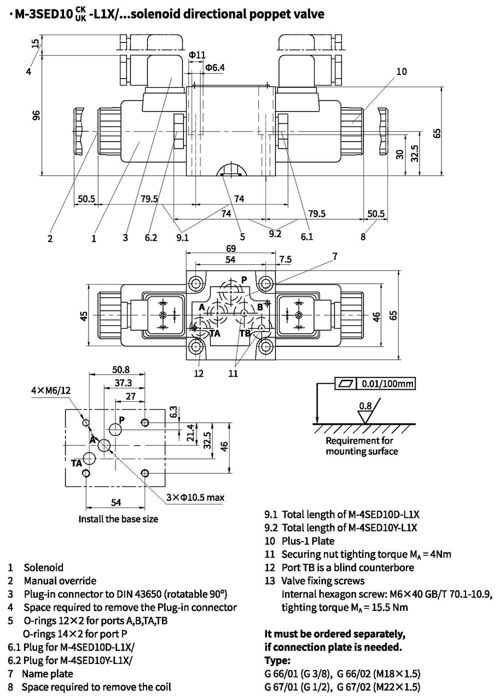
Unit dimensions