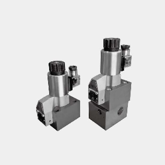
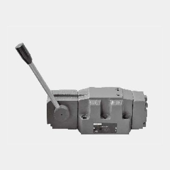
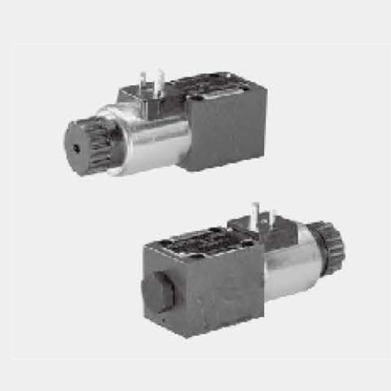
Function and configurationGWE type directional control valve is the directional valve of explosion protection solenoid used to control start, stop and flow direction of oil fluid.The directional contr...
Product Detail
Function and configuration
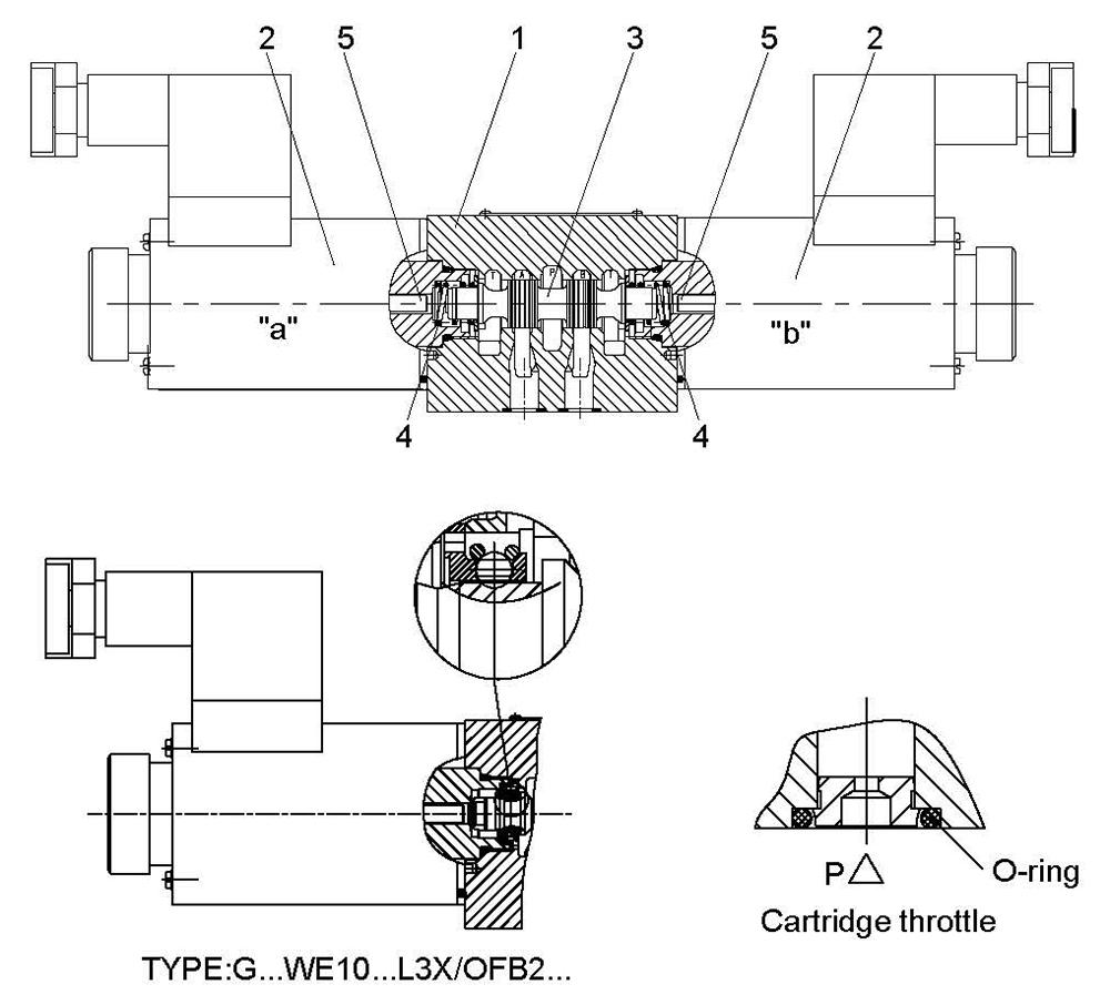
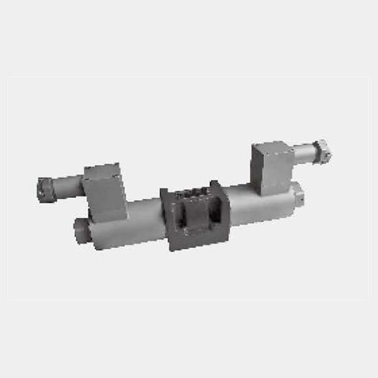
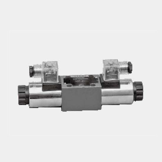
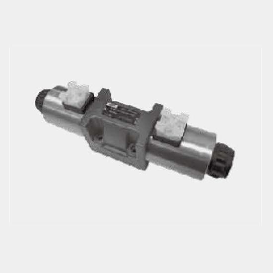
GWE type directional control valve is the directional valve of explosion protection solenoid used to control start, stop and flow direction of oil fluid.
The directional control valves consist of housing (1), one or two solenoids (2), the control spool (3), and one or two return springs (4).
In the de-energised condition the control spool (3) is held in the neutral or initial position by means of return springs (4) (except for pulse spools). The control spool (3) is actuated via wet pin solenoids (2).
To guarantee satisfactory operation care should be taken to ensure that the solenoid pressure chamber is filled with oil.
The control spool(3) is moved to the expected position by solenoid(2) and pushing rod(5), and this gives free-flow from P to A and B to T or P to B and A to T.
When the explosion protection solenoid(2) is powered off, control valve element (3) is pushed to the initial position by reset spring (4).
Type GWE 10 . L3X / O B2...
(Limited to valve element A, C and D)
This type is dual explosion-resistant solenoid 2-position directional valve without a locating mechanism, one of explosion protection solenoids must be powered on in any position, it has not a specific switching position under power-off position.
Type GWE 10 . L3X / OF B2...
(Limited to valve element A, C and D)
This type is dual explosion-resistant solenoid 2-position directional valve with a locator, the valve element can be held at any position and it is unnecessary to continuously electrify the solenoid.
Cartridge throttle
The cartridge throttle is necessary since actual flow may be larger than the performance limits of the valve during switching process.
This cartridge throttle is inserted in the P channel of the directional control valve.
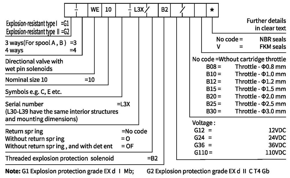
Ordering code
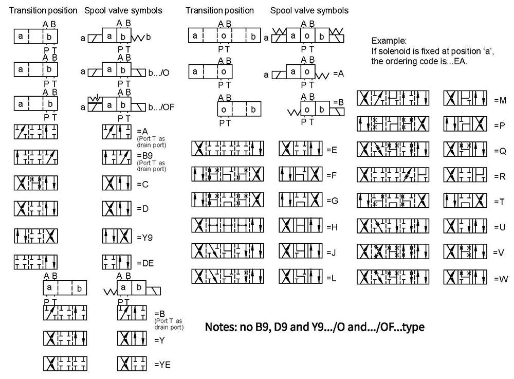
Spool symbols
Technical data
| Fixing position | Optional | |
| Environment temperature range ℃ | -30 to +50 (NBR seal) | |
| -20 to +50 (FKM seal) | ||
| Weight | Single solenoid kg | 5.9 |
| Double solenoids kg | 8.9 | |
| Max.operating pressure | Port P,A,B bar | 315 |
| Port T bar | 210 | |
| when the operating pressure exceeds the permission value, spool symbol A and B must make the port T for draining | ||
| Max.flow-rate | L/min | 120 |
| Flow cross section (switching neutral position) | Version V m㎡ | 11(A/B→T); 10.3(P→A/B) |
| Version W m㎡ | 2.5(A/B→T) | |
| Version Q m㎡ | 5.5(A/B→T) | |
| Fluid | Mineral oil suitable for NBR and FKM seal | |
| Phosphate ester for FKM seal | ||
| Fluid temperature range ℃ | -30 to +80 (NBR seal) | |
| -20 to +80 (FKM seal) | ||
| Viscosity range m㎡/s | 2.8 to 500 | |
| Degree of contamination | Maximum permissible degree of fluid contamination: Class 9. NAS 1638 or 20/18/15,ISO4406 | |
Electrical data
| Type of voltage | DC | |
| Available voltages V | 12,24,36,110 | |
| Voltage tolerance (nominal voltage) % | -15to+10 | |
| Power consumption W | 35 | |
| Duty cycle | Continuous | |
| Switching time to ISO 6403 | ON ms | 45 to 60 |
| OFF ms | 20 to 30 | |
| Switched frequency times/h | To 15000 | |
| Protection class according to DIN 40050 | IP65 | |
| Max.coils tamperature ℃ | +150 | |
Caution: with electrical connections the protective conductor (PE 1/) must be connected according to the relevant regulations.
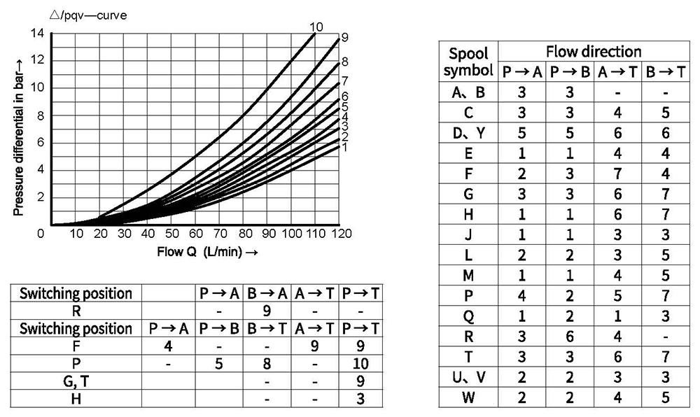
Characteristic curves (Measured at 0oil=40℃±5℃ ,using HLP46)
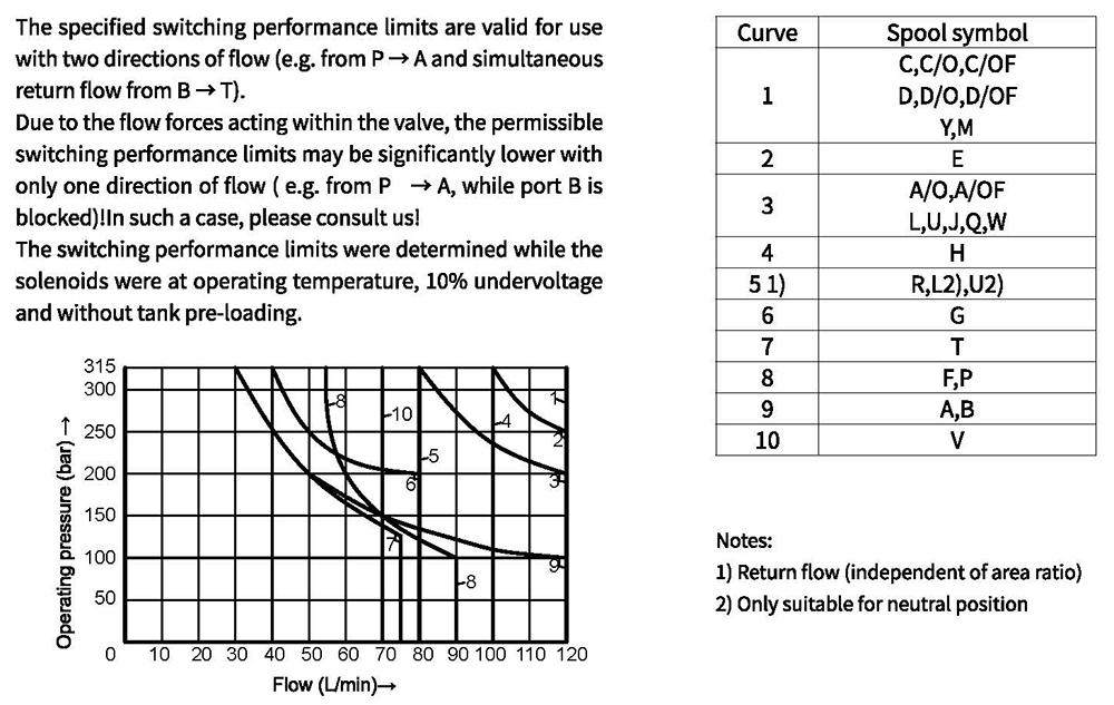
Performance limits (Measured at 9oil=40℃±5℃ ,using HLP46)
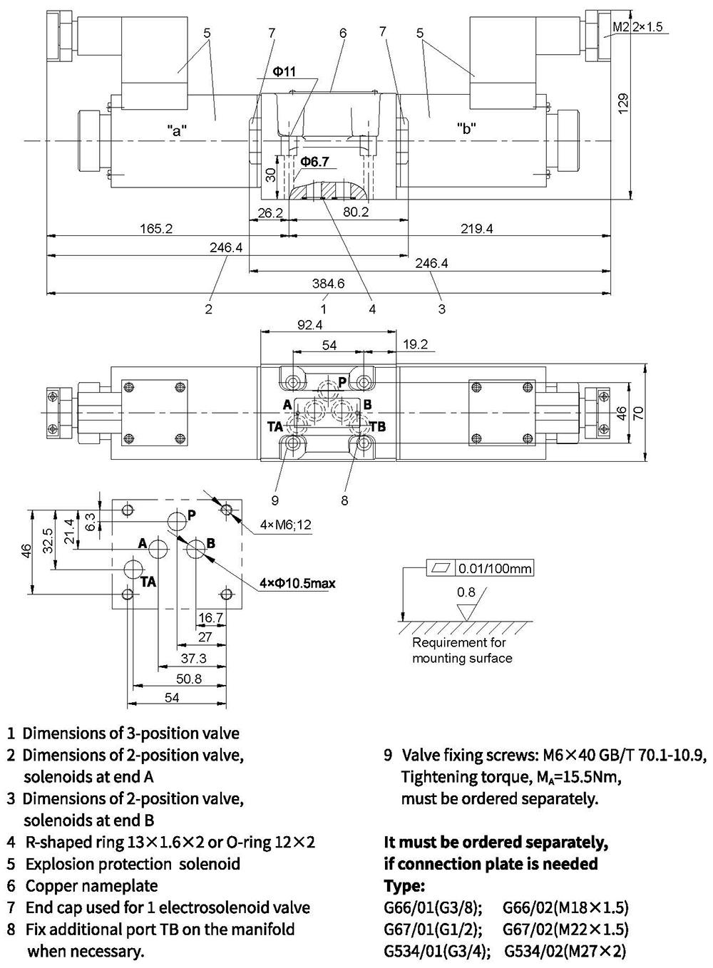
Unit dimensions