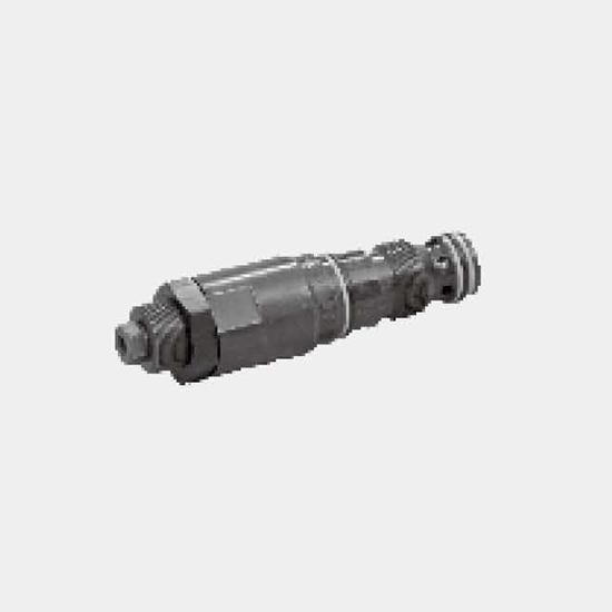
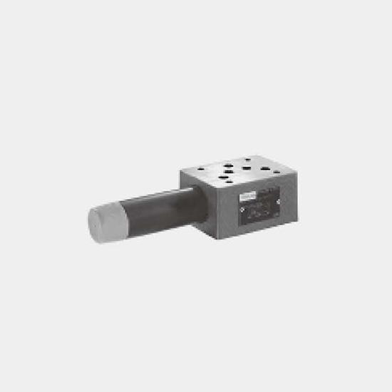
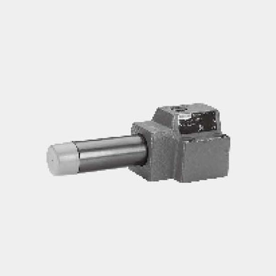
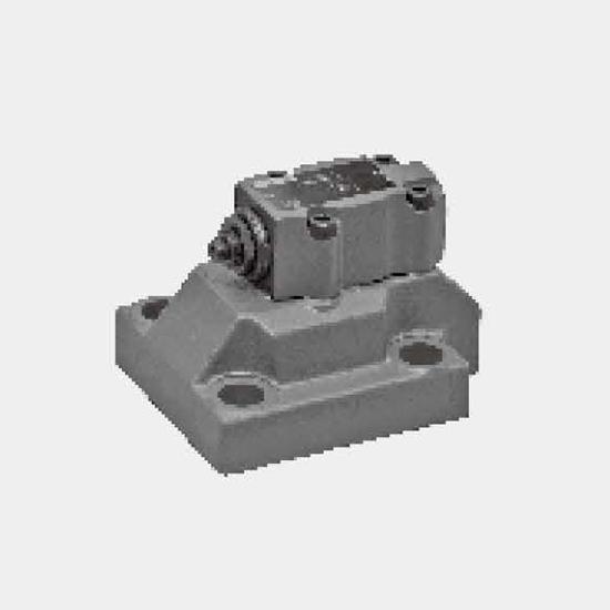
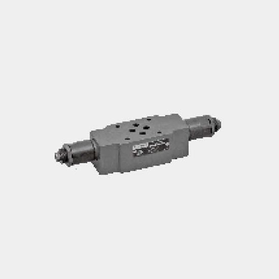
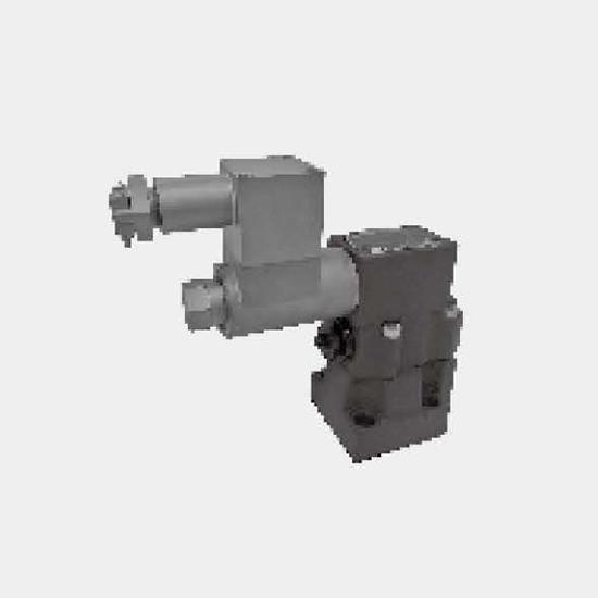
Function and configurationThe DBD pressure relief valves are direct operated, used to limit the pressure of hydraulic system.It comprises the sleeve (1), spring (2), poppet spool with damping (3) and ...
Product Detail
Function and configuration
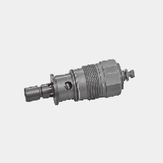
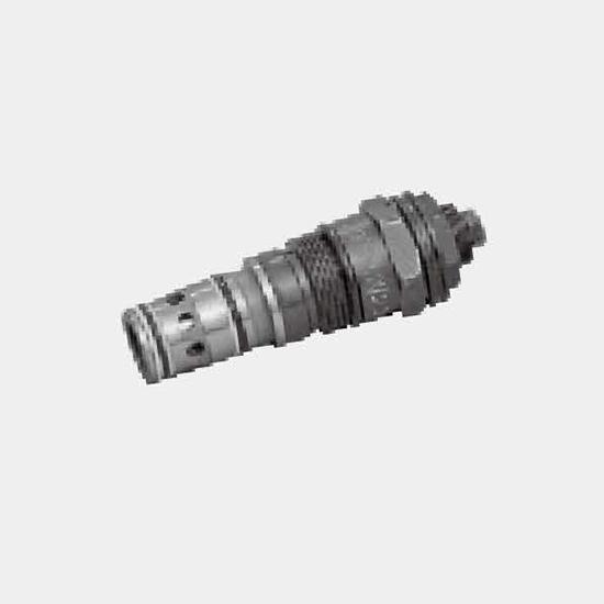
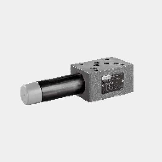
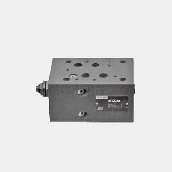
The DBD pressure relief valves are direct operated, used to limit the pressure of hydraulic system.
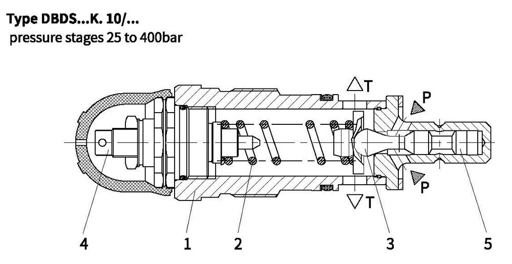
It comprises the sleeve (1), spring (2), poppet spool with damping (3) and pressure adjustment element (4). The system pressure may be set infinitely by the adjustment element. The spring (2) presses poppet spool (3) onto the valve seat.
The channel P is connected to the system and the system pressure affect on the area of poppet spool.
If the pressure in channel P rises in excess of the value set at the spring (2), the poppet spool (3) will opens against the spring (2). The pressure oil flows from channel P to channel T. The stroke of the spool is limited by spin shaft (5).
To gain accurate setting value within the whole pressure range, the pressure scope is divided into 6 pressure ratings, and every rating has a corresponding spring which may be set maximum pressure.
Notes:
Pressure relief valves, direct operated, type DBD has low internal leakage, and higher pressures at flow, and are suitable as a safety valve. Choose pilot operated pressure relief valves if lower adjustable pressure with low internal leakage is needed.
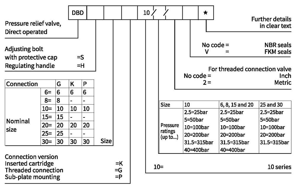
Ordering code
Technical data
| Fluid | Mineral oil suitable for NBR and FKM seal | ||||
| Phosphate ester for FKM seal | |||||
| Fluid temperature range ℃ | -30 to +80 (NBR seal) | ||||
| -20 to +80 (FKM seal) | |||||
| Viscosity range m㎡/s | 10 to 800 | ||||
| Degree of contamination | Maximum permissible degree of fluid contamination: Class 9. NAS 1638 or 20/18/15, ISO4406 | ||||
| Nominal size | 6 and 8 | 10 | 15 and 20 | 25 and 30 | |
| Operating pressure range | Inlet bar | Up to 400 | up to 400 | up to 400 | up to 315 |
| Outlet bar | 315 | ||||
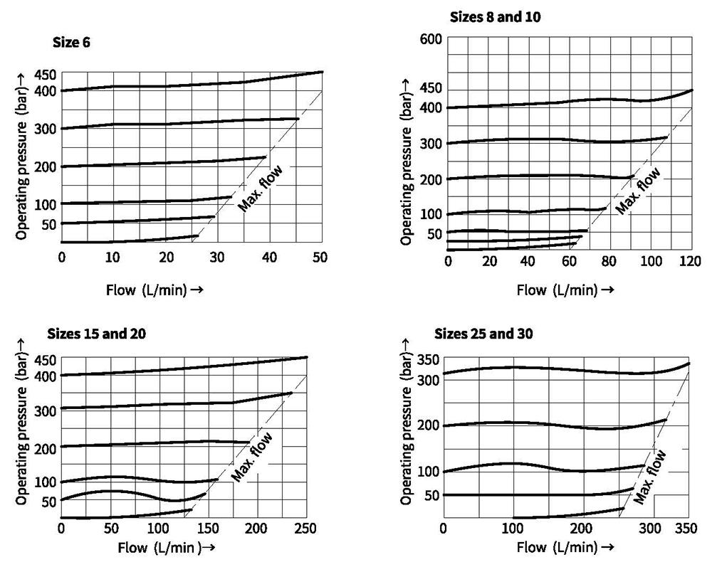
| Max.flow-rate L/min | See the Characteristic curve | ||||
Performance curves(Measured at oil =40°C +5°C, using HLP46)
Unit dimensions
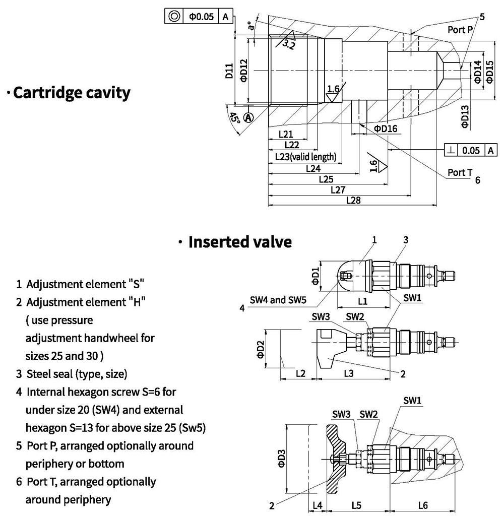
| Size | Weight (kg) | D1 | D2 | D3 | L1 | L2 | 13 | L4 | L5 | L6 | SW1 | Torque(Nm) | SW3 | SW4 | SW5 | ||
| 6 | Approx.0.4 | 34 | 60 | - | 72 | 11 | 88 | - | - | 64 | 32 | 80 | 19 | 6 - | - | ||
| 10 | Approx.0.5 | 38 | 68 | 79 | 75 | 36 | 150 | ||||||||||
| 20 | Approx.1 | 48 | 65 | 77 | 106 | 46 | 250 | ||||||||||
| 30 | Approx.2.3 | 63 | - | 80 | 83 | - | - | 11 | 56 | 131 | 60 | 450 | 13 | ||||
| Size | D11 | D12 | D13 | D14 | D15 | D16 | L21 | L22 | L23 | L24 | L25 | L27 | L28 | a | |||
| 6 | M28x1.5 | 25H9 | 6 | 15 | 24.9 | 6 | 15 | 19 | 39 | 35 | 45 | 56.5±5.5 | 65 | 15 | |||
| 10 | M35x1.5 | 32H9 | 10 | 18.5 | 31.9 | 10 | 18 | 23 | 35 | 41 | 52 | 67.5±7.5 | 80 | ||||
| 20 | M45x1.5 | 40H9 | 20 | 24 | 39.9 | 20 | 21 | 27 | 45 | 54 | 70 | 91.5±8.5 | 110 | 20 | |||
| 30 | M60x2 | 55H9 | 30 | 38.75 | 54.9 | 30 | 23 | 29 | 60 | 84 | 113.5±11.5 | 140 | |||||
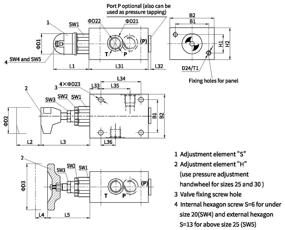
Unit dimensions
· Threaded connection valve
| Size | Weight(kg) | B1 | B2 | D1 | D2 | D3 | D21 | D22 | D23 | D24 | |||||||||
| 6 | Approx.1.6 | 45 | 60 | 34 | 60 | - | 25 | G1/4;M14x1.5 | 6.6 | M6 | |||||||||
| (8)+10 | Approx.3.7 | 60 | 80 | 38 | (28)34 | G3/8 M18x1.5; G1/2 M22x1.5 | 9 | M8 | |||||||||||
| (15)+20 | Approx.6.9 | 70 | 100 | 48 | (42)47 | G3/4 M27x2; G1 M33x2 | |||||||||||||
| (25)+30 | Approx.15.2 | 100 | 130 | 63 | - | 80 | (56)61 | G1 1/4 M42x2;G1 1/2 48x2 | 11 | M10 | |||||||||
| Size | L1 | L2 | L3 | L4 | L5 | L31 | L32 | L33 | L34 | L35 | L36 | SW1 | SW2 | SW3 | SW4 | SW5 | H1 | H2 | T1 |
| 6 | 72 | 11 | 83 | - | - | 80 | 2 | 15 | 55 | 40 | 20 | 32 | 30 | 19 | 6 | - | 25 | 40 | 10 |
| (8)+10 | 68 | 79 | 100 | (2) 3 | 20 | 70 | 49 | 21 | 36 | 40 | 60 | 20 | |||||||
| (15)+20 | 65 | 77 | 135 | (3) 4 | 100 | 65 | 34 | 46 | 36 | 50 | 70 | ||||||||
| (25) +30 | 83 | - | - | 11 | 56 | 180 | 4 | 25 | 130 | 85 | 35 | 60 | 46 | - | 13 | 60 | 90 | 25 | |
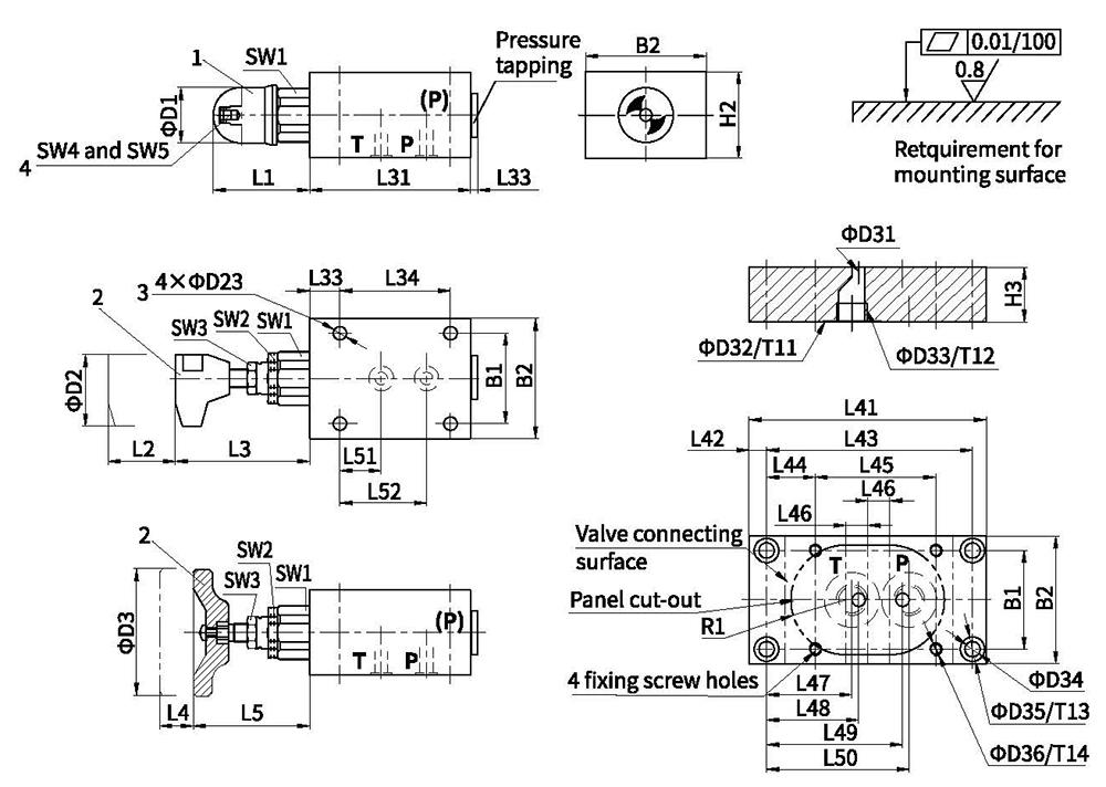
Unit dimensions
. Sub-plate mounting valve
| Size | O-ring (P and T) | Dimension of pressure tapping | Valve fixing hole (GB/T70.1-10.9) | Torque(Nm) |
| 6 | 8.75x1.8 | G1/4 | M6x50 | Approx.10 |
| 10 | 12.3x2.4 | G1/2 | M8x70 | Approx.25 |
| 20 | 22x3 | M27x2 | M8x90 | |
| 30 | 34x3 | M42x2 | M10x110 | Approx.50 |
1 Adjustment element "S”
2 Adjustment element "H"(Sizes 25 and 30 use pressure adjustment handwheel)
3 Valve fixing screw hole
4 Internal hexagon screw S=6 for under size 20(SW4) and external hexaon S=13 for above size 25 (SW5)
| Size | Weight(kg) ) | B1 | B2 | D1 | D2 | D3 | D23 | H2 | L1 | L2 | L3 | L4 | L5 | L31 | L32 | L33 | L34 | SW1 | SW2 | SW3 | SW4 | SW5 | |
| 6 | Approx.1.6 | 45 | 60 | 34 | 60 | - | 6.6 | 40 | 72 | 11 | 83 | - | - | 80 | 2 | 15 | 55 | 32 | 30 | 19 | 6 | - | |
| 10 | Approx.3.7 | 60 | 80 | 38 | 9 | 60 | 68 | 79 | 100 | 3 | 20 | 70 | 36 | ||||||||||
| 20 | Approx.7.1 | 70 | 100 | 48 | 70 | 65 | 77 | 135 | 4 | 100 | 46 | 36 | |||||||||||
| 30 | Approx.15.7 | 100 | 130 | 63 | - | 80 | 11 | 90 | 83 | - | 11 | 56 | 180 | 4 | 25 | 130 | 60 | 46 | - | 13 | |||
| Size | Sub-plate type | Weight(k g) | D31 | D32 | D33 | D34 | D35 | H3 | L41 | ||||||||||||||
| 6 | G300/1 | 约1.5 | 6 | 25 | G1/4 | 7 | 11 | 25 | 110 | ||||||||||||||
| 10 | (G301/1) G302/1 | 约2 | 10 | (28)34 | (G3/8)G | 135 | |||||||||||||||||
| 20 | (G303/1) G304/1 | 约5.5 | (15)20 | (42)47 | (G3/4)G1 | 11.5 | 17.5 | 40 | 170 | ||||||||||||||
| 30 | (G305/1) G306/1 | 约8 | 30 | (56)61 | (G1 1/4) G11/2 | 190 | |||||||||||||||||
| D36 | L42 | L43 | L44 | L45 | L46 | L47 | L48 | L49 | L50 | L51 | L52 | T11 | T12 | T13 | T14 | R1 | |||||||
| M6 | 8 | 94 | 22 | 55 | 10 | 39 | 42 | 62 | 65 | 20 | 40 | 1 | 15 | 9 | 15 | 25+2 | |||||||
| M8 | 10 | 115 | 27.5 | 70 | 12.5 | 40.5 | 48.5 | 72.5 | 80.5 | 21 | 45 | (15)16 | |||||||||||
| 15 | 140 | 20 | 100 | 20 | (45)42 | 54 | 85 | (94)97 | 34 | 65 | 20 | 13 | (12)22 | 40+3 | |||||||||
| M10 | 12.5 | 165 | 17.5 | 130 | 22.5 | 42 | 52.5 | 102.5 | (113)117 | 35 | 85 | 24 | 11.5 | 22 | 55+4 | ||||||||