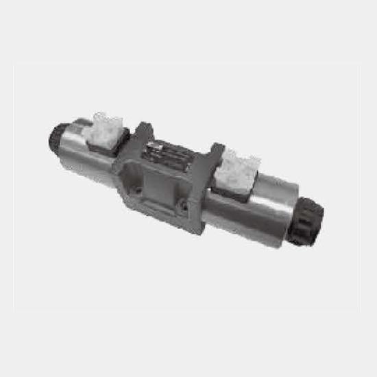
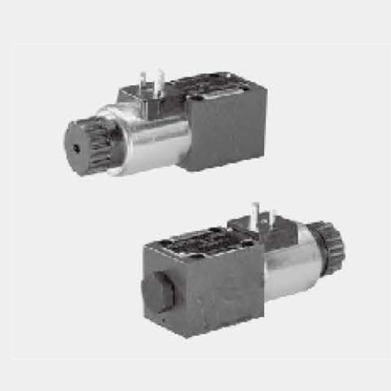
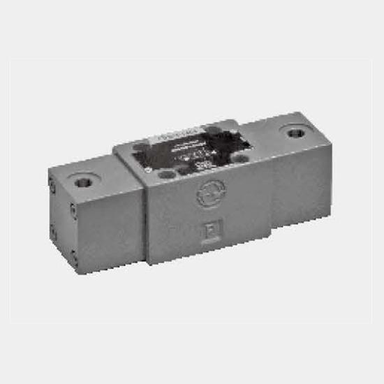
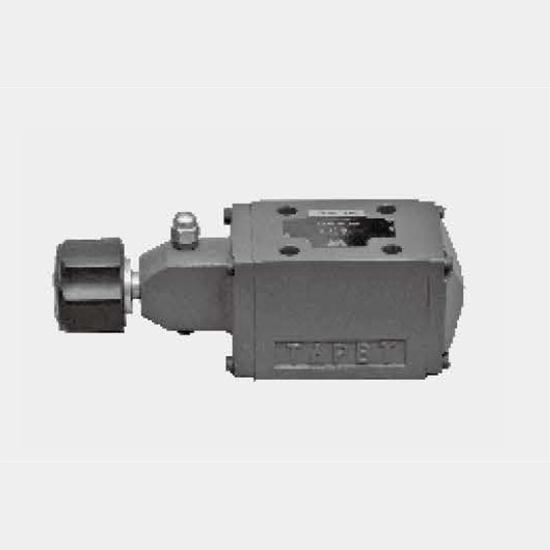
FunctionDirectional valves, type WMR/U6.. are mechanical directional spool valves with roller plunger. There are 2 position 3way, 2 position 4 way and 3 position 4 way valves with many versions of spo...
Product Detail
Function
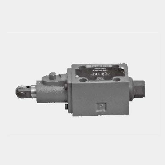
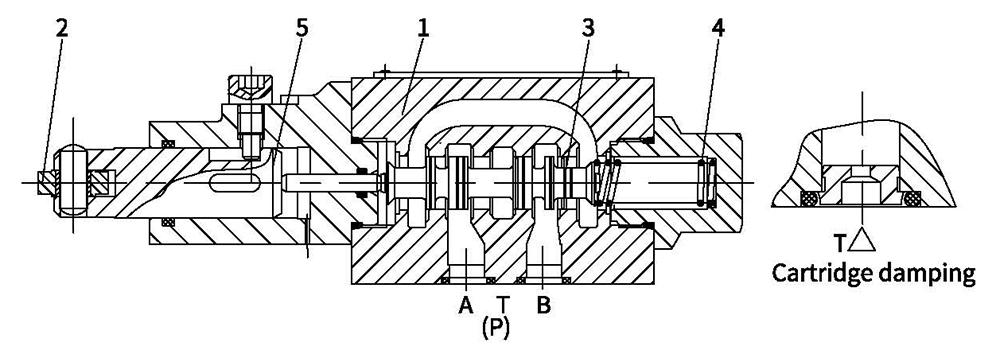
Directional valves, type WMR/U6.. are mechanical directional spool valves with roller plunger. There are 2 position 3way, 2 position 4 way and 3 position 4 way valves with many versions of spool symbols, the roller/plunger can be rotated by 90°.
The valves consist basically of the housing (1), roller/plunger (2), spool (3), return springs (4), and pushing rod (5). In the unoperated condition, the spool (3) is held in the initial position by the return spring, while in operated condition, the spool (3) is pushed to the expected position by roller/plunger (2) conquering the return springs (4).
Cartridge throttle
The use of a throttle insert is required, when, due to given operating conditions, flows can occur during the switching processes that exceed the performance limit of the valve
These throttles are to be inserted into the P-channel of the directional valve.
 11
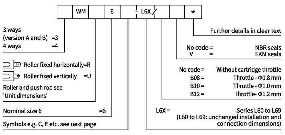
Ordering code
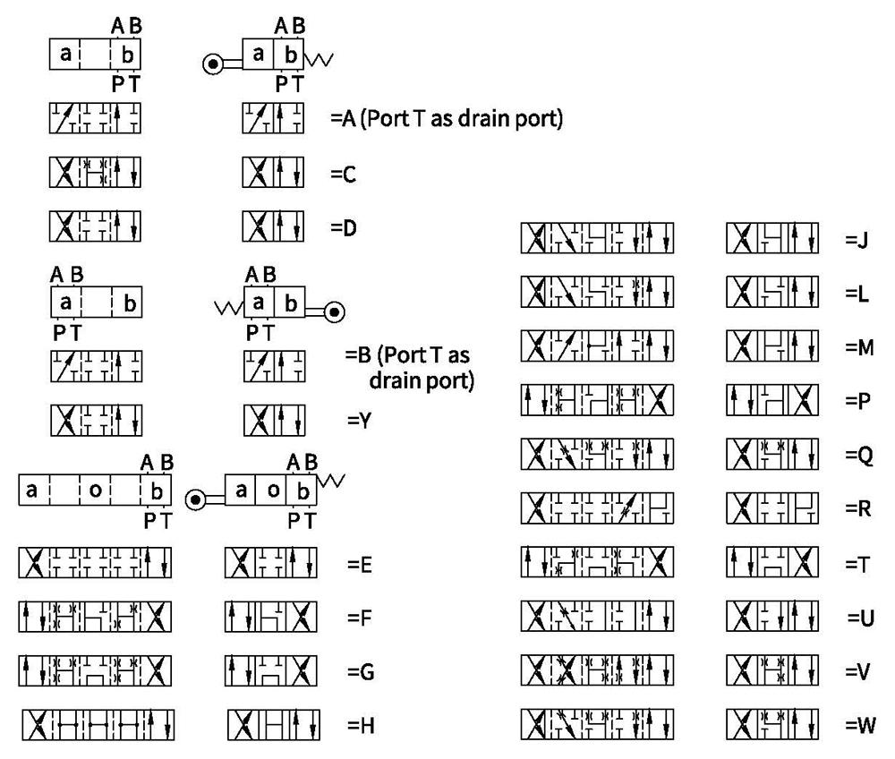
Symbols
Technical data
| Fluid temperature range ℃ | -30 to+80 (NBR seal) | |
| -20 to+80 (FKM seal) | ||
| Max.operating pressure | Port A,B,P bar | 315 |
| Port T bar | 60 | |
| Max. flow-rate L/min | 60 | |
| Flow cross section (switching neutral position) | Type Q m㎡ | For symbol Q 6% of nominal cross section |
| Type W m㎡ | For symbol W 3% of nominal cross section | |
| Fluid | Mineral oil, Phosphate ester | |
| Viscosity range m㎡/s | 2.8 to 500 | |
| Degree of contamination | Maximum permissible degree of fluid contamination: Class 9. NAS 1638 or 20/18/15,ISO4406 | |
| Weight kg | 1.4 | |
Operating limitation
Because of the adhesive effect, the switching function of the valves depends on the filtration. In order to achieve the specified admissible flow values, we recommend full flow filtration with 25 μm. The flow forces acting within the valves also affect the flow performance. With 4 way valves the specified flow data thus apply to normal operation with 2 volume flow directions (e.g. from P to A and at the same time return flow from B to T) (see table).
If only one flow direction is available, in critical cases, the admissible flow can be significantly smaller (e.g. when using a 4 way valve as 3 way valve, due to blocked connection A or B).
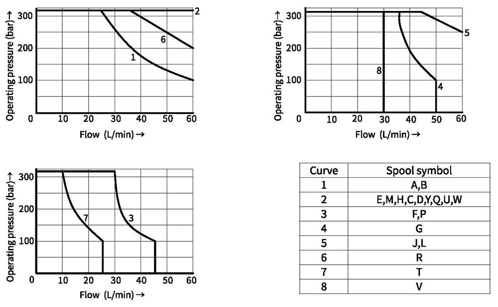
Characteristic curves (Measured at θₐᵢᵣ=40℃±5℃, using Lₚₐₛₛ)
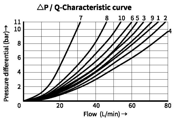
7 Symbol "R" in switched positions B → A
8 Symbol "G" and "T" in neutral position P → T
9 Symbol "H" in neutral position P → T
| Spool symbol | Flow direction | |||
| PtoA | P to B | Ato T | B to T | |
| AB | 3 | 3 | - | - |
| C | 1 | 1 | 3 | 1 |
| DY | 5 | 5 | 3 | 3 |
| E | 3 | 3 | 1 | 1 |
| F | 1 | 3 | 1 | 1 |
| T | 10 | 10 | 9 | 9 |
| H | 2 | 4 | 2 | 2 |
| JQ | 1 | 1 | 2 | 1 |
| L | 3 | 3 | 4 | 9 |
| M | 2 | 4 | 3 | 3 |
| P | 3 | 1 | 1 | 1 |
| R | 5 | 5 | 4 | - |
| V | 1 | 2 | 1 | 1 |
| W | 1 | 1 | 2 | 2 |
| U | 3 | 3 | 9 | 4 |
| G | 6 | 6 | 9 | 9 |
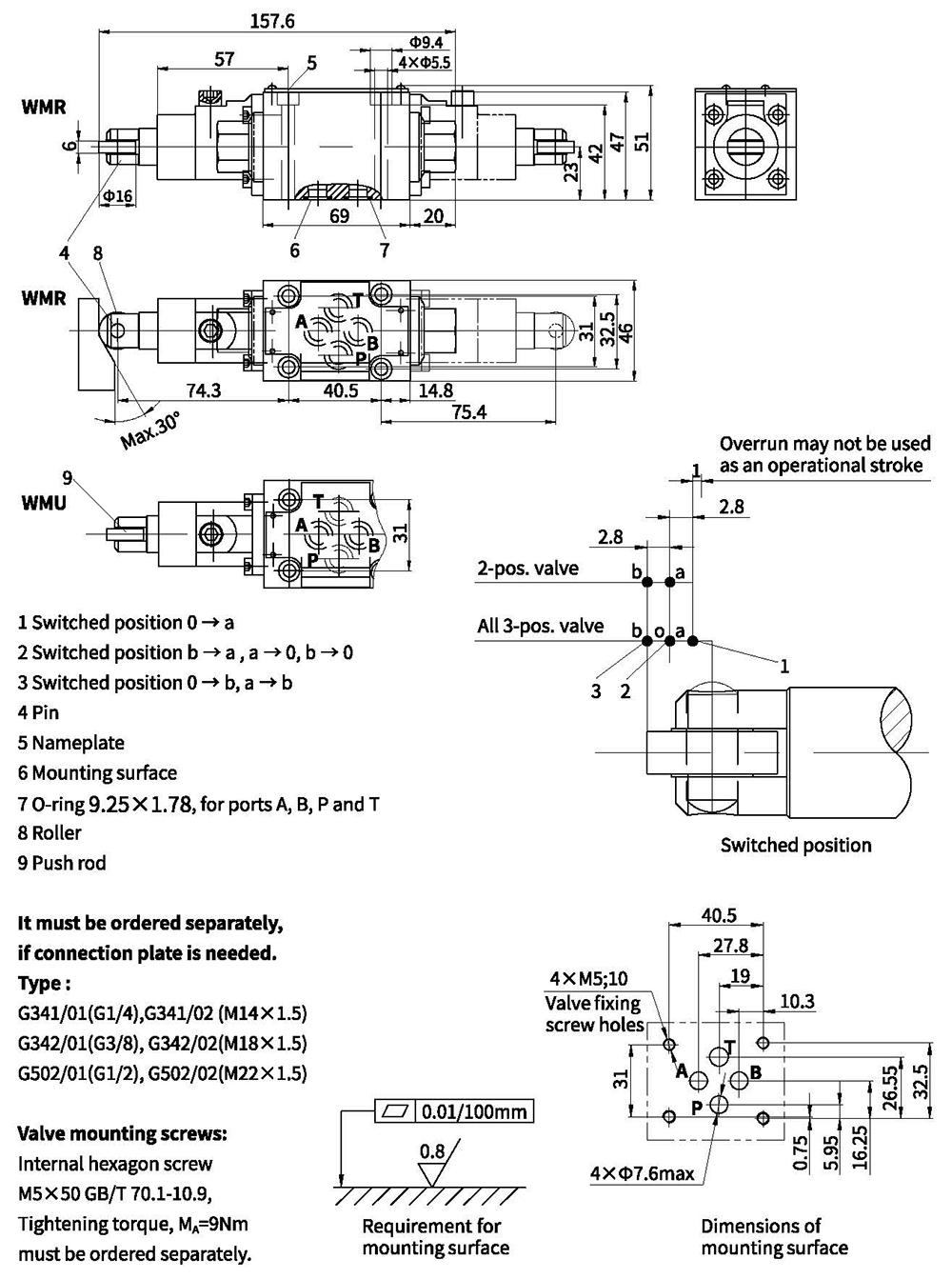
Unit dimensions