Function and configurationThe valve types DRE/DREM are pilot operated pressure reducing valves. They are used for pressure reduction.The valves consist of the pilot valve (1) with proportional solenoi...
Product Detail
Function and configuration
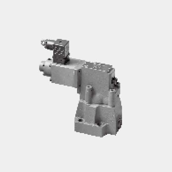
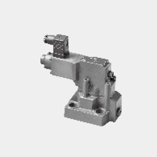
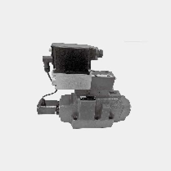
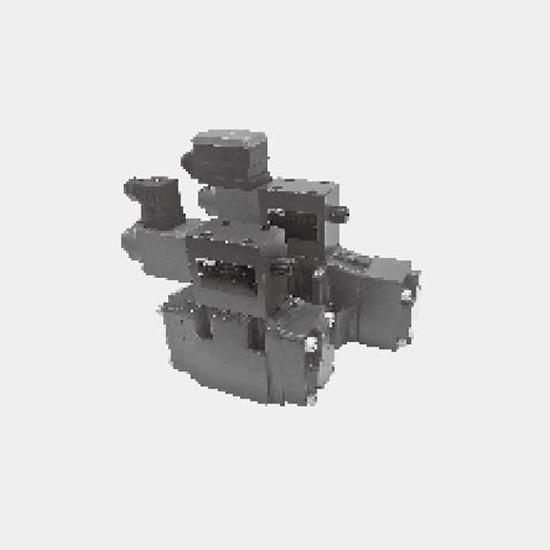
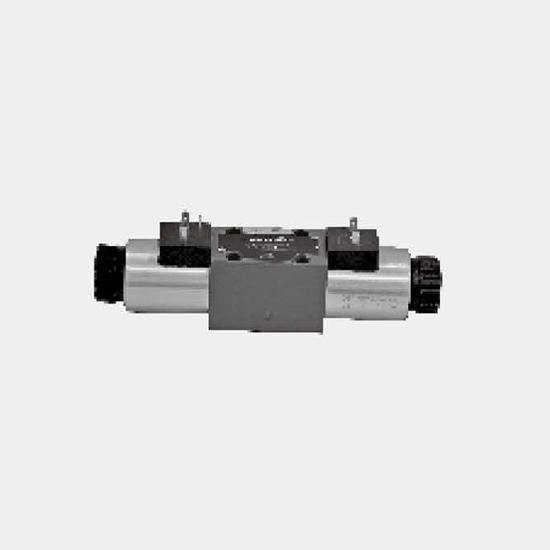
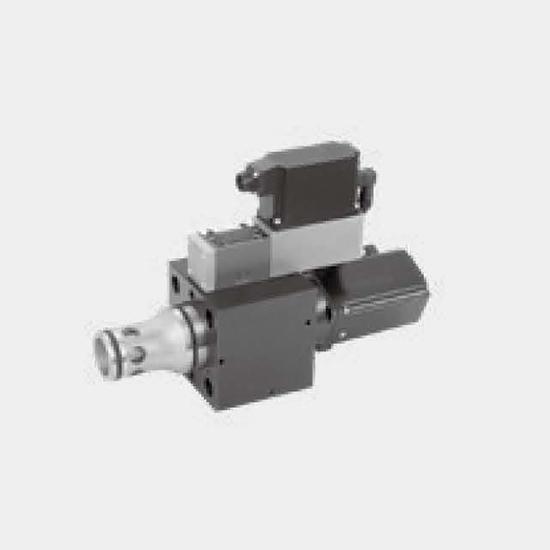
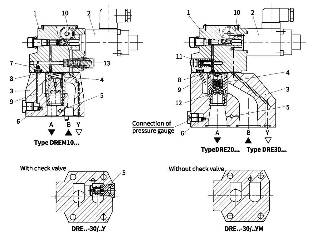
The valve types DRE/DREM are pilot operated pressure reducing valves. They are used for pressure reduction.
The valves consist of the pilot valve (1) with proportional solenoid (2), main valve (3) with main spool assembly (4), as well as an optional check valve (5).
Type DRE10...
The setting of the pressure in port A is dependent on the voltage present at the proportional solenoids (2).
At static, proportional solenoids (2) breakaway, the connection from B to A opens and fluid can flow freely from Port B to port A via main spool (4). When valve works, pressure fluid from port A acts on the spring load side of the main spool (4) via pilot valve with throttle (6), (7) and (8), and at the same time acts on spool (10) effected by electromagnetic force. If pressure at port A exceeds the preset value of the corresponding proportional solenoid (2), then the spool (10) opens.
Signal and pilot fluid is from port A, and fluid flows to tank through spool (10) and port Y. There is pressure differential on main spool (4) which makes itself into controller position and keeps flow constant pressure in port A as same as the setting value of the proportional solenoids (2). If the pressure in the port A increases and the main spool (4) is closed, little fluid will flow to tank via hole (9) and port Y. In order to allow free-flow from port A to B a check valve (5) can be fitted.
Type DRE20...and DRE30...
Same principle with DRE10 in function and pilot oil drains out from channel (9) and port B. There is a flow control valve (11) fixed in the pilot valve (1) to relief the pilot oil. And the overload protector (12) in the port A can prevent the pressure from abnormally high when flow Q=0.
Type DREM...
A spring loaded pressure relief valve (13) can be optionally installed to prevent higher pressure in port A caused by abnormal peak voltage of proportional solenoids.
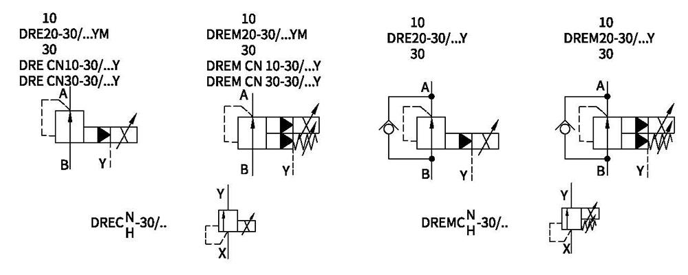
Symbols
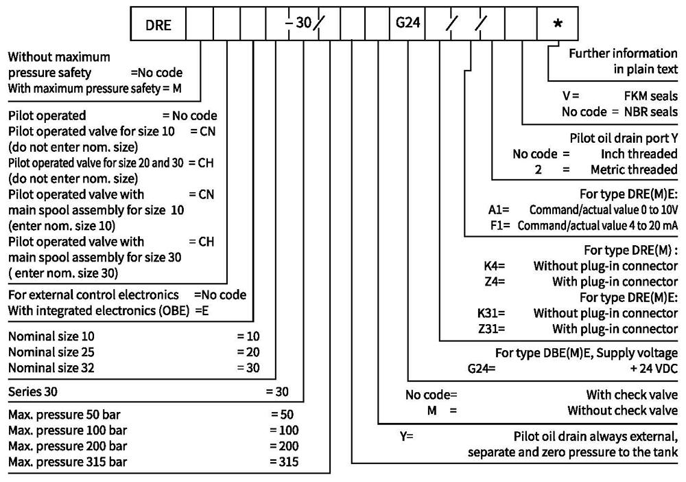
Ordering code
Technical data
| Fluid | Mineral oil suitable for NBR and FKM seal | ||||
| Phosphate ester for FKM seal | |||||
| Fluid temperature range | ℃ | -30 to +80 (NBR seal) | |||
| -20 to +80(FKM seal) | |||||
| Viscosity range | m㎡/s | 2.8 to 380 | |||
| Degree of contamination | Maximum permissible degree of fluid contamination: Class 9. NAS 1638 or 20/18/15,ISO4406 | ||||
| Max. operating pressure | Port A,B | bar | 315 | ||
| Port Y | Back to tank with zero pressure | ||||
| Max.setting pressure | Port A | bar | 50;100;200;315 | ||
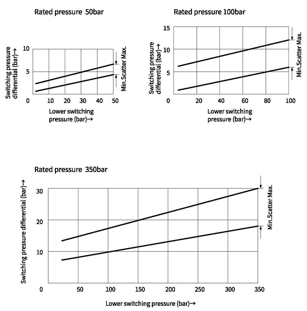
| Min.setting pressure | Port A | Dependent with Q (see characteristic curves) | |||
| Pressure at current value 0 in port A | =Min. settable pressure (see characteristic curves) | ||||
| Max. pressure limitation (stepless) | Setting pressure | setting range under max.pressure limition | |||
| 50 bar | 10-60+20 bar | ||||
| 100 bar | 10-120+20 bar | ||||
| 200 bar | 10-220+20 bar | ||||
| 315 bar | 10-340+20 bar | ||||
| Max.pressure limition setting range | When rated pressure=50 bar, between 60~80 bar | ||||
| When rated pressure=100 bar, between 120~140 bar | |||||
| When rated pressure=200 bar, between 220~240 bar | |||||
| When rated pressure=315 bar, between 340~360 bar | |||||
| Nominal size | 10 | 25 | 32 | ||
| Max.flow-rate | L/min | 80 | 200 | 300 | |
| Pilot flow-rate (for pilot valve) | L/min | 0.7to 2 | |||
| Linearity | ±3.5% | ||||
| Repeatability | <±2% | ||||
| Magnetic creeping | with shimmy | without shimmy | |||
| ±2.5% Pmax | ±4.5% Pmax | ||||
| Shifting time | 100 to 300ms (dependent with the system) | ||||
| Electrical | ||
| Supply voltage | DC | |
| Min.solenoid current | mA | 100 |
| Max.solenoid current | mA | 800 |
| Coil resistance | 19.5Ω at 20℃,Max. warm value :28.8Ω | |
| Working status | Continuous | |
| Max.working enviromental temperature | +50℃ | |
| Electrical connection | Plug-in connector to DIN EN 175301-803/ISO 4400 | |
| Valve protection to DIN 40 050 | IP 65 | |
| Ampilfier | VT2000 | |
Proportional amplifier (Can be ordered separately)
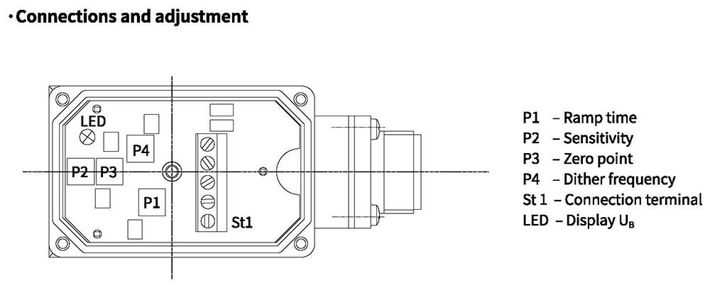
Electrical connections, plug-in connectors
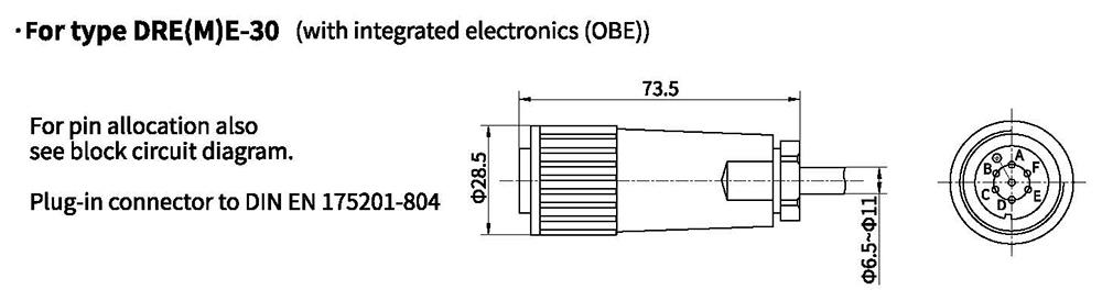
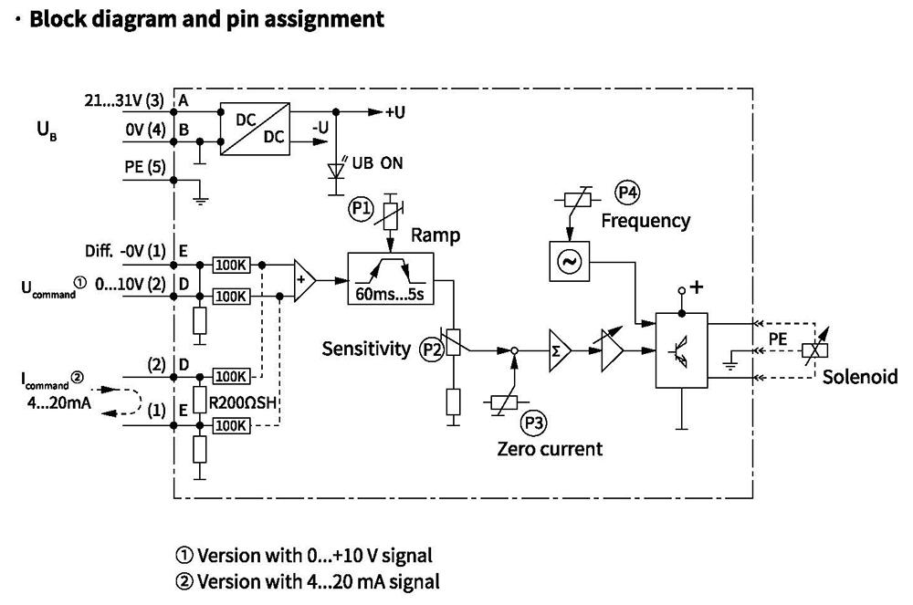
·Component plug allocation
| Contact | Interface A1 signal | Interface F1 signal | |
| Supply voltage | A | 24 VDC(U(t)=21V至31V) | |
| B | GND | ||
| C | n.c.1) | ||
| Differential amplifier input | D | ±10V,Re>50KΩ | 4至20mA,Re>100Ω |
| E | reference potentional command value | ||
| F | n.c.1) | ||
1)Contacts C and F must not be connected!
Electrical connections, plug-in connectors
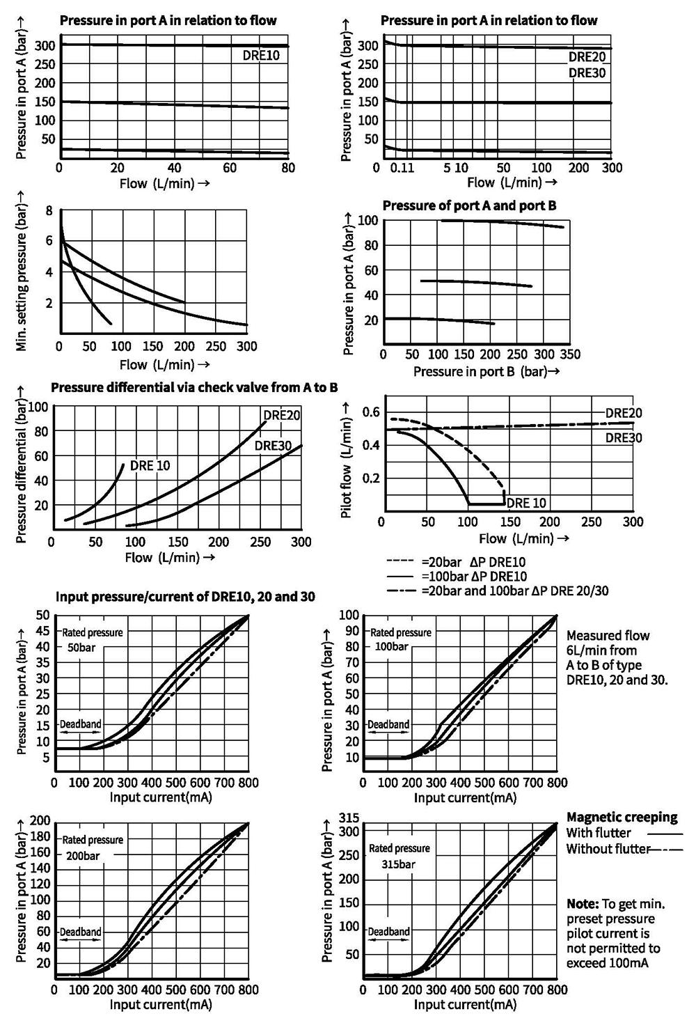
Characteristic curves(Measured at oil =40°C +5°C, using HLP46)
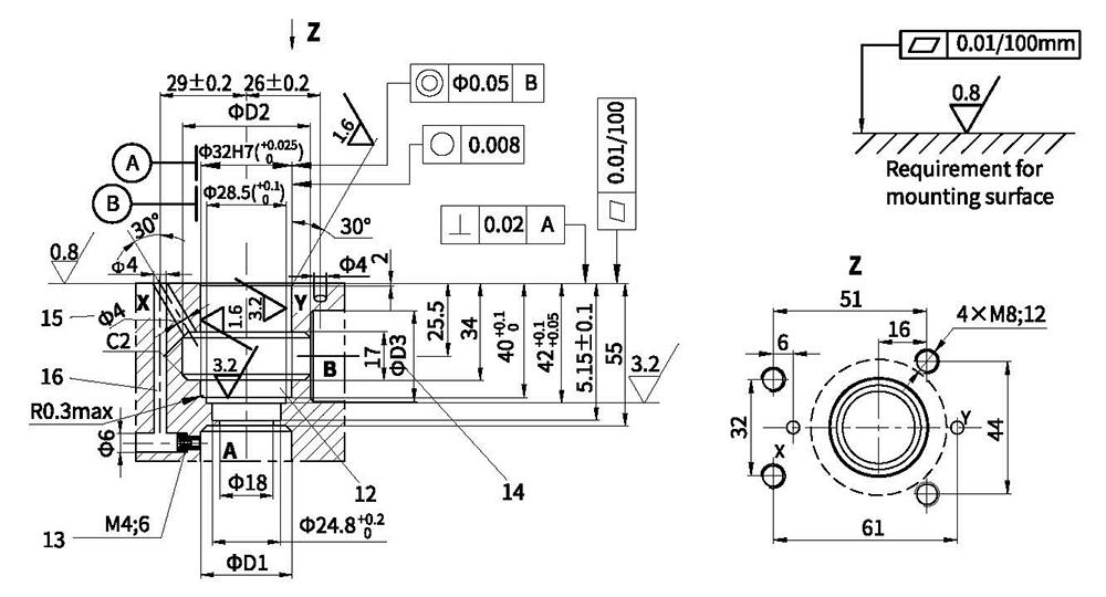
Unit dimensions
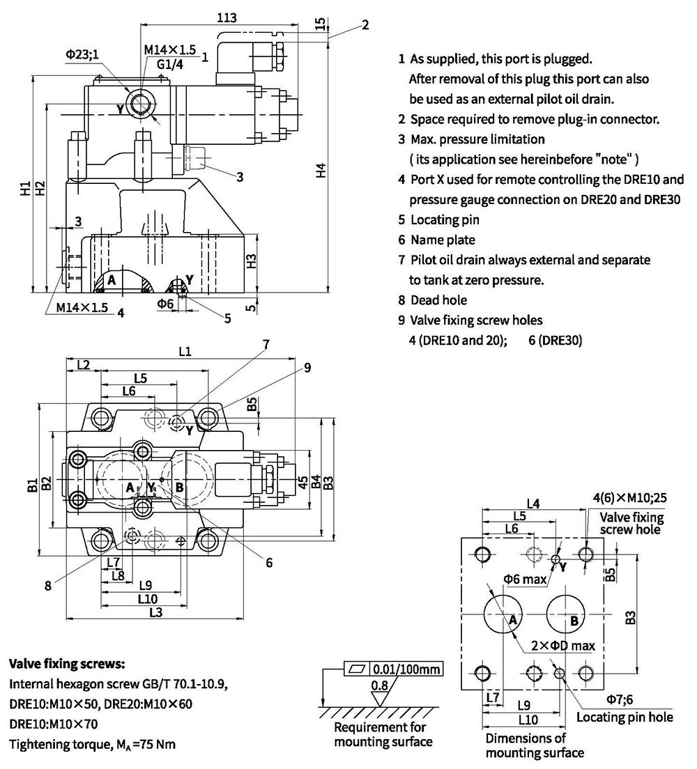
| Size | B1 | B2 | B3 | B4 | B5 | O-ring (port A and B) | O-ring (port X and Y) | D | H4 | |||||
| 10 | 85 | 50 | 66.7 | 58.8 | 7.9 | 17.12x2.62 | 9.25x1.78 | 13 | 188 | |||||
| 25 | 102 | 59.5 | 79.4 | 73 | 6.4 | 28.17x3.53 | 9.25x1.78 | 22 | 198 | |||||
| 32 | 120 | 76 | 96.8 | 92.8 | 3.8 | 34.52x3.53 | 9.25x1.78 | 30 | 206 | |||||
| Size | L1 | L2 | L3 | L4 | L5 | L6 | L7 | L8 | L9 | L10 | H1 | H2 | H3 | Weight |
| 10 | 181 | 35.5 | 96 | 42.9 | 21.5 | - | 7.2 | 21.5 | 31.8 | 35.8 | 152 | 136.5 | 28 | 5.2kg |
| 25 | 177 | 33.5 | 112 | 60.3 | 39.7 | - | 11.1 | 20.6 | 44.5 | 49.2 | 162 | 146.5 | 38 | 6.3kg |
| 32 | 176.5 | 28 | 140 | 84.2 | 59.5 | 42.1 | 16.7 | 24.6 | 62.7 | 67.5 | 170 | 154.5 | 46 | 8.6kg |
Unit dimensions
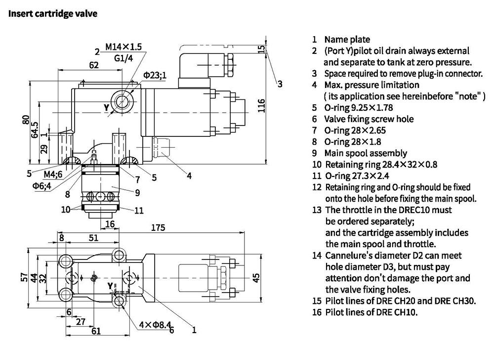
| Size | D1 | D2 | D3 | Main spool assembly ordering code | Valve fixing screws | Tightening torque | Weight | |
| 10 | 10 | 40 | 10 | 306727 | 306728 | 4pcs M8x40 GB/T70.1-10.9 Internal hexagon screw | 20Nm | 3kg |
| 25 | 20 | 45 | 20 | 306729 | 306730 | |||
| 32 | 30 | 45 | 30 | (NBR) | (FKM) | |||