Function and configurationConstructionThe valve consists of three main assemblies:Pilot valve (1) with control spool and sleeve, return springs, control solenoid and inductive position transducerMain ...
Product Detail
Function and configuration
Construction
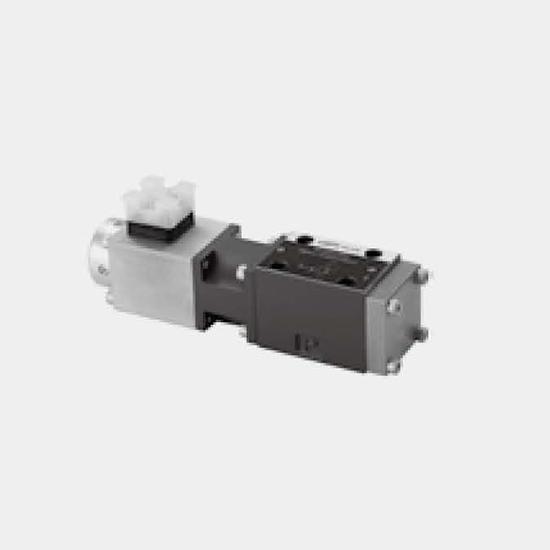
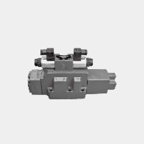
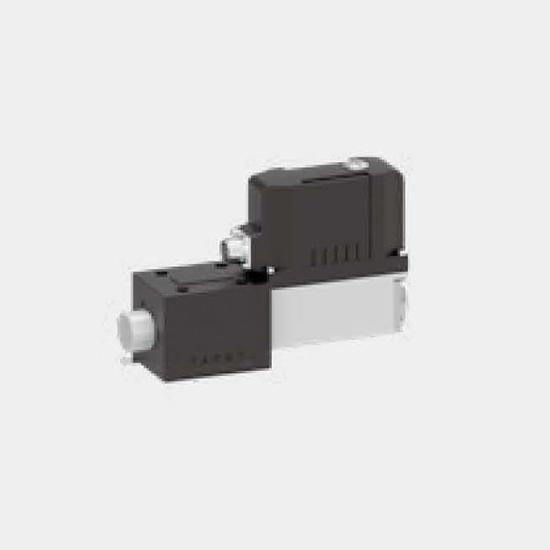
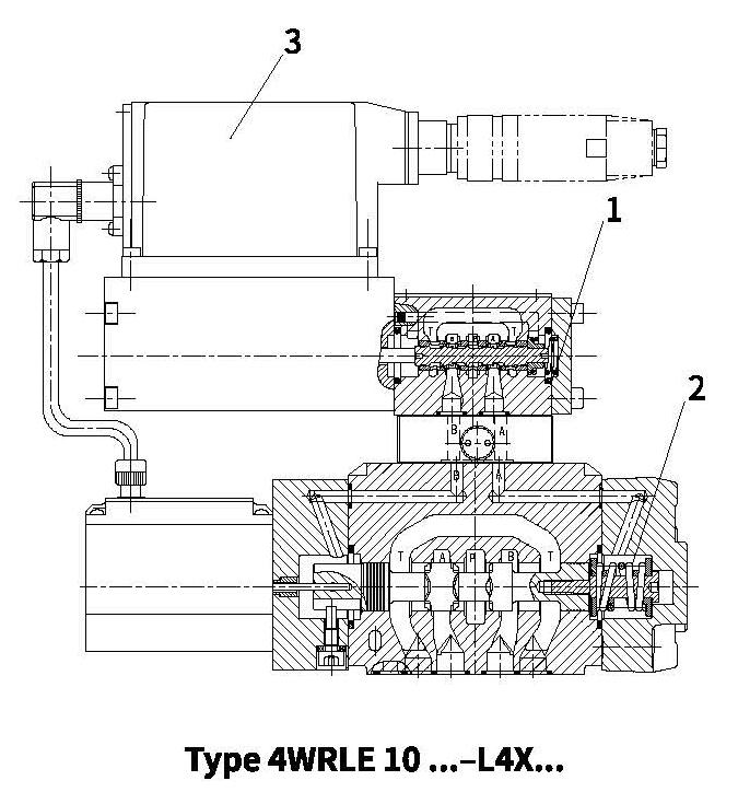
The valve consists of three main assemblies:
Pilot valve (1) with control spool and sleeve, return springs, control solenoid and inductive position transducer
Main stage (2) with centering springs and position feedback
On-board trigger electronics (3)
Functional description
When the control solenoid is not actuated, the control spool is held by springs in the fail-safe position, and the main stage spool remains in its spring-centered mid position.
In the on-board electronics, the pre-defined setpoint is compared with the actual value for the position of the main stage control spool. In the event of an error signal, the control solenoid is actuated, and the pilot spool is moved as the magnetic force changes.
The flow released through the control cross-sections causes the main control spool to move. The spool stroke is controlled proportionately to the setpoint of 0.5...10V between 20...100 %.
If the input setpoint is < ±0.5V, the control spool is held in the spring-centered, overlapped mid position.
Power failure
In the event of a power failure or an open circuit, the onboard electronics cut off the electricity to the control solenoid and the pilot spool moves to the fail-safe position, relieving the control oil chambers of the main stage. The main stage control spool is held by springs in mid position.
Symbols
Ordering code
Technical data
| General | NG10 | NG16 | NG25 | NG27 | |
| Design | Spool type valve, pilot operated | ||||
| Construction | Servo solenoid directional control valve NG6, with position controller for pilot valve and main stage | ||||
| Type of mounting | Subplate, mounting hole configuration NG10...27 to ISO 4401-.. | ||||
| Installation position | . Optional | ||||
| Ambient temperature range | ℃ | -20...+50 | |||
| Weight | kg | 8.35 | 10 | 18 | 18 |
| Vibration resistance, test condition | Max.25g,shaken in 3 dimensions (24 h) | ||||
| Hydraulic (measured with HLP 6, 90=4±5℃ 0℃ | ) | |||||
| Pressure fluid | Hydraulic oil to DIN 51524...535, other fluids after prior consultation | |||||
| Viscosity range | Recommended | m㎡/s | 20...100 | |||
| Max.permitted | m㎡/s | 10...800 | ||||
| Maximum permissible degree of contamination of pressure fluid. Purity class to ISO 4406 (c) | Class 18/16/13 | |||||
| Flow direction | See symbol | |||||
| Nominal flow at Δ p=5 bar per notch 2) | L/min | see ordering code | ||||
| Max.working pressure | Ports P,A,B External control oil inlet | bar | 350 | 350 | 350 | 280 |
| Ports P, A, B Internal control oil inlet | bar | 280 | ||||
| Ports T,X,Y | bar | 250 | ||||
| Min. control oil pressure in "pilot stage" | bar | 10 | ||||
| Qmax | L/min | 170 | 450 | 900 | 1000 | |
| QN pilot valve Δp=35 bar | L/min | 4 | 12 | 24 | 24 | |
| Leakage of pilot valve at 100 bar | L/min | <180 | <350 | <500 | <500 | |
| Leakage of main stage (symbols' "E") at 100 bar | L/min | <0.25 | <0.4 | <0.6 | <0.6 | |
| Static/Dynamic | ||||||
| Hysteresis | % | <0.1, scarcely measurable | ||||
| Manufacturing tolerance for Qmax | % | ≤10 | ||||
| Response time for signal change | at X=100 bar | 0...100% | 25 | 26 | 32 | 32 |
| 0...10% | 14 | 15 | 18 | 18 | ||
| at X=10 bar | 0...100% | 85 | 80 | 120 | 120 | |
| 0...10% | 50 | 30 | 50 | 50 | ||
| Switch-off behavior | After electrical switch-off: pilot valve in fail-safe. Main stage moves to spring-centered "mid position" | |||||
| Thermal drift | Zero point displacement<1% at ΔT=40℃ | |||||
| Zero adjustment | Adjustable ±5% via valve amplifier | |||||
1) The purity classes stated for the components must be complied with in hydraulic systems.
Effective filtration prevents problems and also extends the service life of components.
Technical data
| Electric pilot valve NG6, trigger electronics integrated in the valve | ||
| Cyclic duration factor % | 100 ED | |
| Degree of protection | IP 65 to DIN 40050 and IEC 14434/5 | |
| Connection | Plug-in connector 6P+PE, DIN 43563 | |
| Power supply Terminal A: Terminal B: OV | 24 V DC min.21 V DC/max. 40 V DC Ripple max.2 V DC | |
| Power consumption | 40 VA max. | |
| External fuse AF | 2.5 | |
| Input,"Standard"version Terminal D:UF Terminal E: | Differential amplifier, R1=100kΩ 0...±10V OV | |
| Max. differential input voltage at OV | D→B E→B | max.18V DC |
| Test signal, "Standard" version Terminal F: Utest Terminal C: | LVDT 0...±10V Reference 0 V | |
| Protective conductor and screen | See pin assignment | |
| Recommended cable | See pin assignment Up to 20m 7x0.75m㎡ Up to 40m 7x1m㎡ | |
| Calibration | Overlap and P-A at +8V, calibrated at the factory, see valve characteristic curve | |
Electrical connection
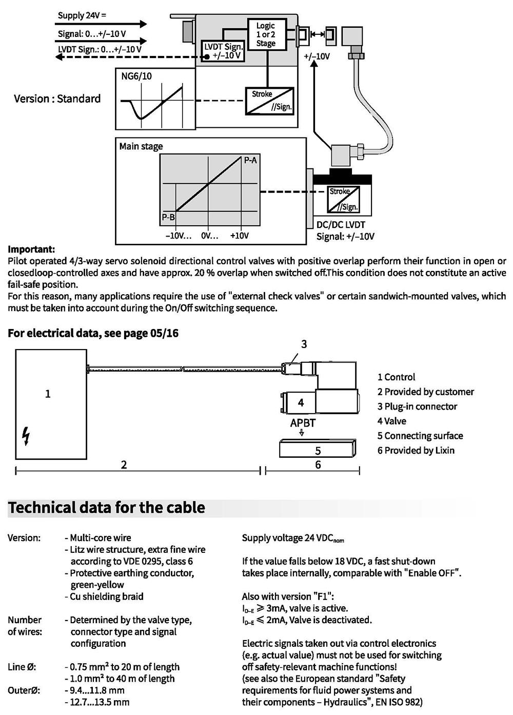
On-board electronics
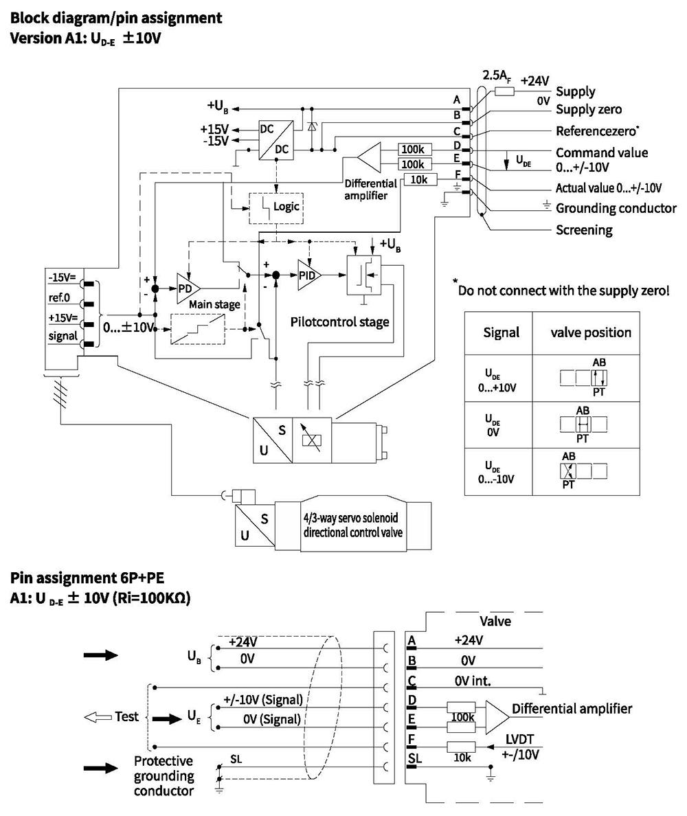
Integrated electronics
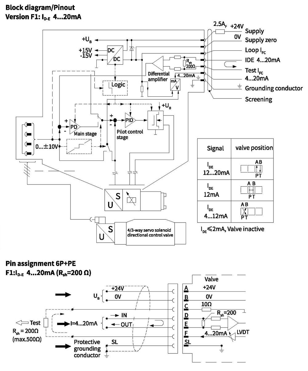
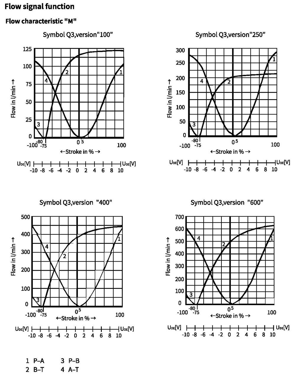
Characteristic curves(measured with HLP46, oil=40°C +5°C)
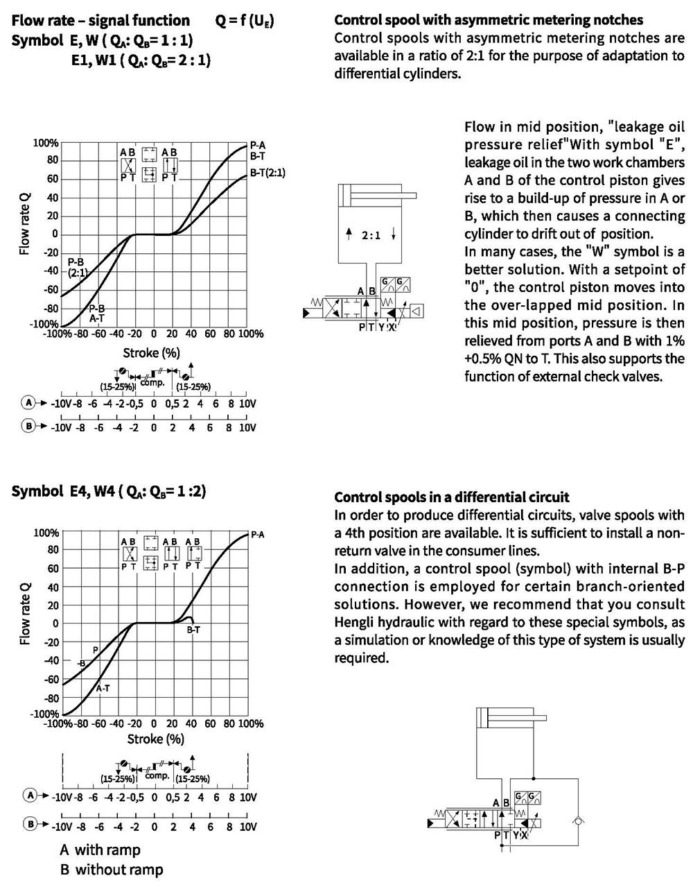
Characteristic curves(measured with HLP46, oil=40°C +5°C, Ap=5 bar/control edge)
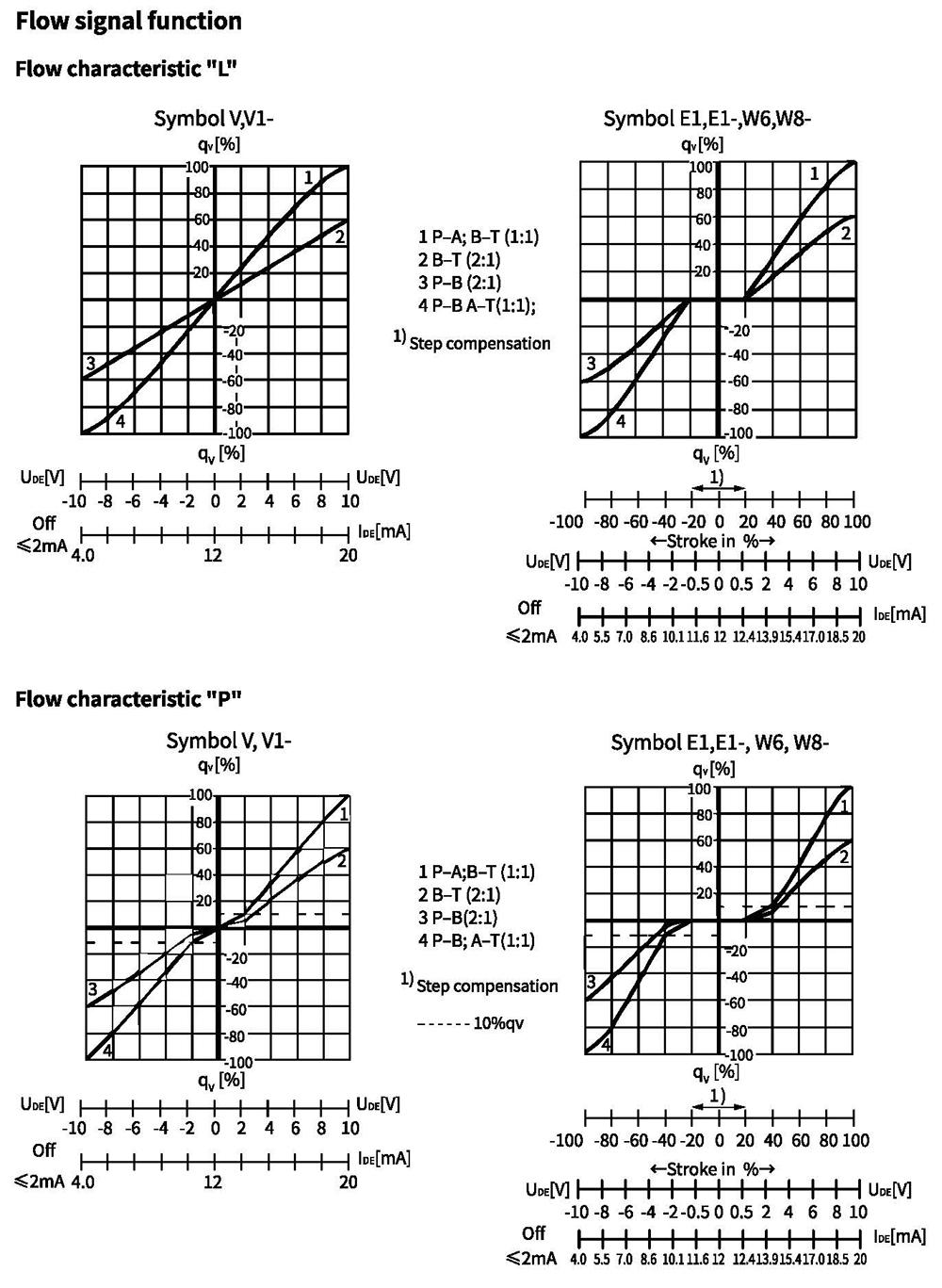
Characteristic curves(measured with HLP46, oil=40°C +5°C, Ap=5 bar/control edge)
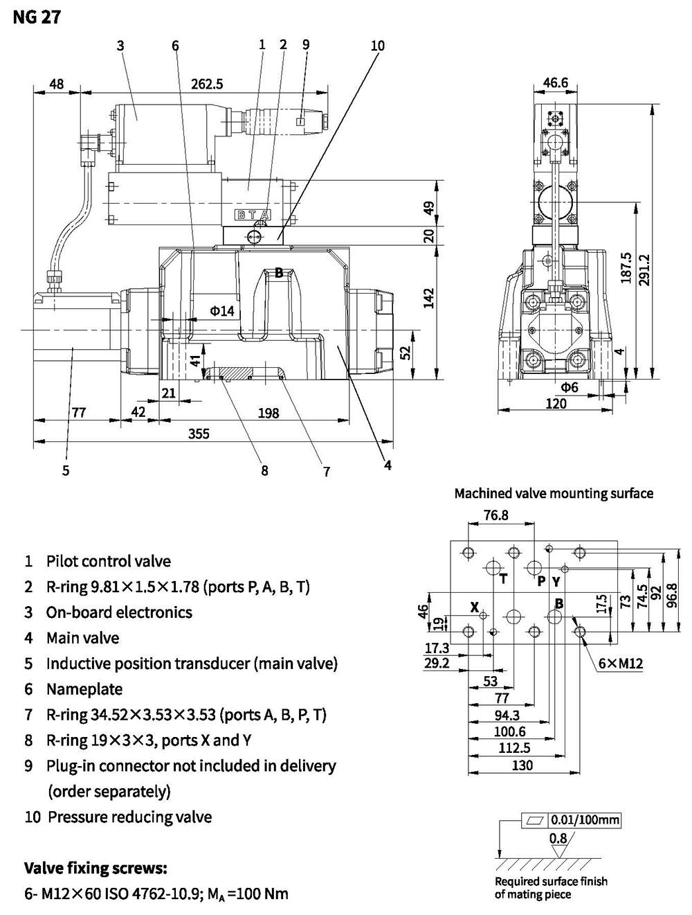
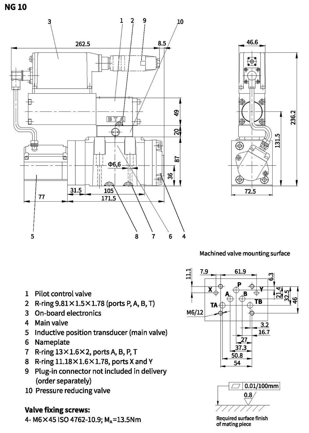
Unit dimensions
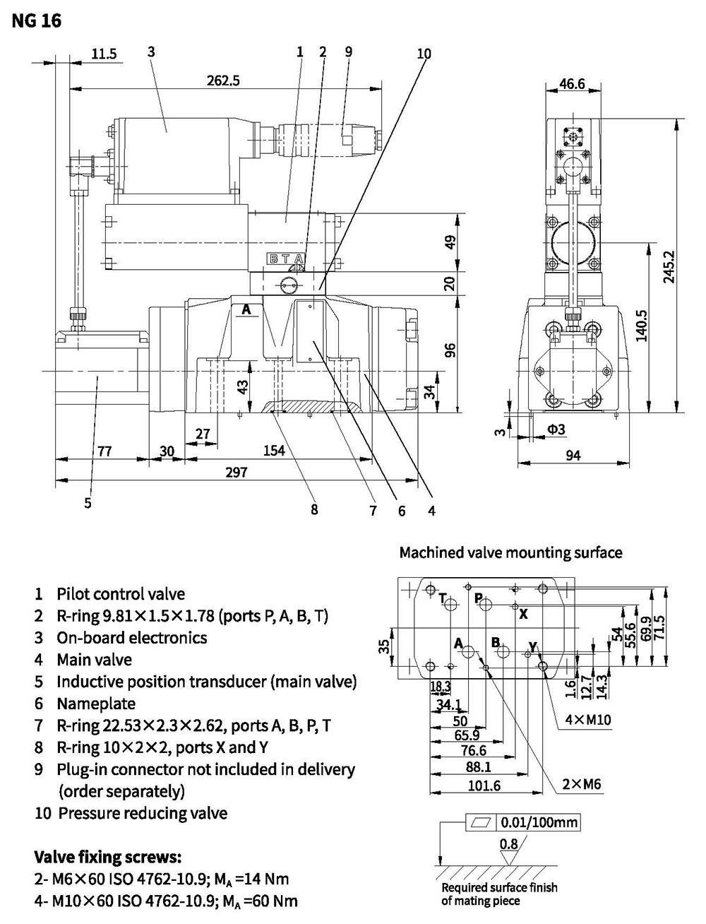
Unit dimensions
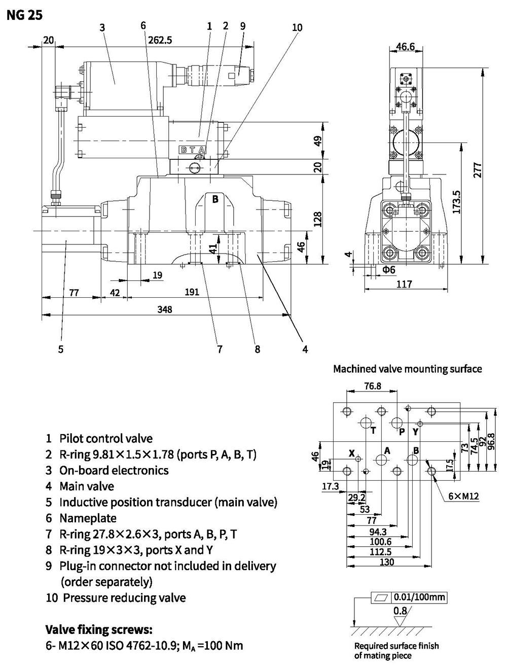
Unit dimensions
Unit dimensions