Function and configurationValves of types 3DRE(M) and 3DRE(M)E are electrically pilot operated 3-way pressure reducing valves with pressure relief function for the actuator. They are used to reduce a ...
Product Detail
Function and configuration
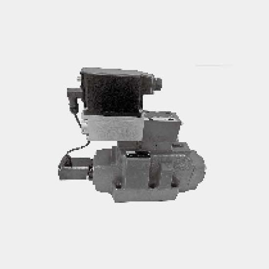
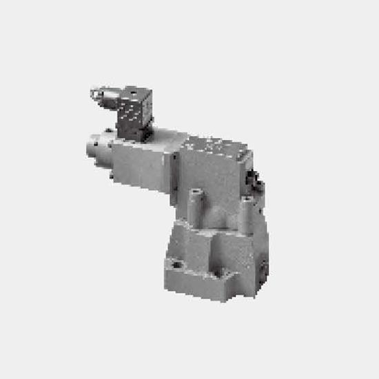
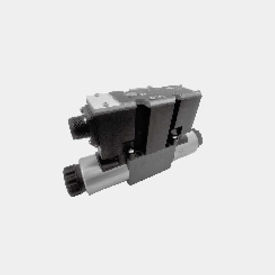
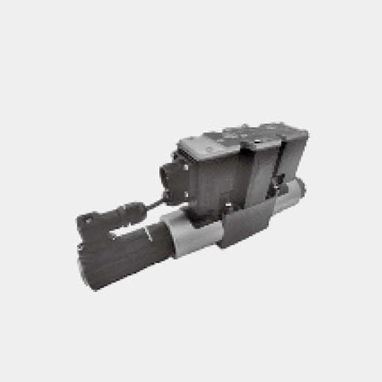
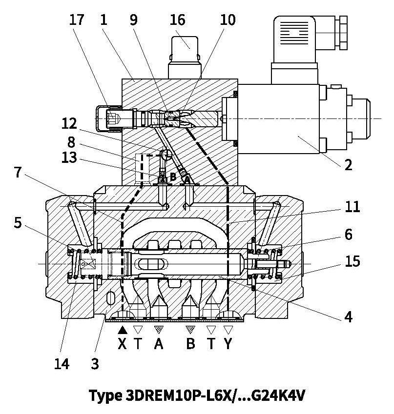
Valves of types 3DRE(M) and 3DRE(M)E are electrically pilot operated 3-way pressure reducing valves with pressure relief function for the actuator. They are used to reduce a system pressure.
Technical structure:
The valves consist of three main assemblies:
Pilot valve (1) optionally with maximum pressure relief function (16)
Proportional solenoid (2)
Main valve (3) with main spool (4)
Function:
General function:
Command value-related adjustment of the pressure to be reduced in channel A by proportional solenoid (2).
When no pressure is applied in port P, main spool (4) is held by springs (5) and (6) in the central position. Here, the connections from P to A and A to T are closed. Pilot oil flows from bore (7) via flow controller (8), pilot valve (1) to orifice (9), throttling gap (10), pipe (11) to port Y. This port must be connected at zero pressure to the tank.
Pressure reduction:
Build-up of pilot pressure in control chamber (12) as a function of the command value. Pressure is built up in spring chamber (14) via orifice (13) and the main spool is shifted to the right. Hydraulic fluid flows from P to A. The actuator pressure in port A is applied to spring chamber (15).
An increase in the pressure in port A to the pressure set on pilot valve (1) causes main spool (4) to be pushed to the left. The pressure in port A becomes virtually the same as the pressure set on pilot valve (1).
Pressure relief function:
When the pressure in port A exceeds the pressure set on pilot valve (1), main spool (4) is shifted further to the left. This causes the connection from A to T to open and limits the pressure applied in port A to the set command value.
Type 3DREM:
The valve is optionally available with an additional spring-loaded pilot valve (16) to provide a maximum pressure relief function.
Types 3DREE and 3DREME
with integrated electronics (OBE):
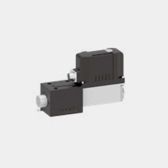
In terms of function and structure, these valves correspond to types 3DRE and 3DREM, except for the integrated electronics.
The electronics receives the supply and command value voltage via cable socket.
The command value/pressure characteristic curve (zero point on spindle (17) and the gradient are adjusted in the factory with narrow tolerances on the Imax potentiometer in the electronics.
The ramp time for pressure build-up and pressure reduction can be adjusted independently of each other with the help of two potentiometers.
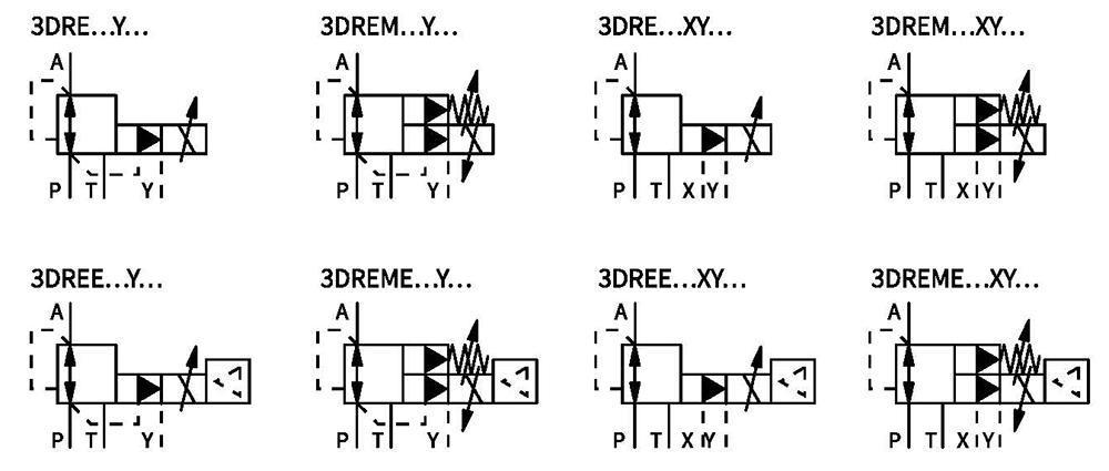
Symbols
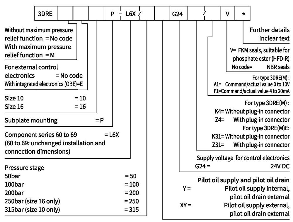
Ordering code
Technical data
| General | |||
| Size | 10 | 16 | |
| Weight | 3DRE and 3DREM kg | 7.7 | 10.2 |
| 3DREE and 3DREME kg | 7.8 | 10.3 | |
| Installation orientation | Optional, preferably horizontal | ||
| Storage temperature range ℃ | -20 to+80 | ||
| Ambient temperature range | 3DRE and 3DREM ℃ | -20to+70 | |
| 3DREE and 3DREME ℃ | -20to+50 | ||
| Hydraulic (measured with HLP46; 0onl=40℃±5℃ and p =100bar) | ||||||
| Size | 10 | 16 | ||||
| Max. operating pressure | Ports P,A and X bar | 315 | P and X=315; A=250 | |||
| Port Y bar | separately and at zero pressure to tank | |||||
| Max.set pressure in channel A | Pressure stage50bar bar | 50 | 50 | |||
| Pressure stage100bar bar | 100 | 100 | ||||
| Pressure stage200bar bar | 200 | 200 | ||||
| Pressure stage250bar bar | 250 | |||||
| Pressure stage315bar bar | 315 | |||||
| Min. set pressure | channel A at zero command value | see characteristic curves | ||||
| Maximum pressure relief function (infinitely adjustable) | Pressure stage 50bar bar | Pressure adjustment range | 30 to 70 | Factor setting | to 70bar | |
| Pressure stage 100bar bar | 50 to 130 | to 130bar | ||||
| Pressure stage 200bar bar | 90 to 230 | to 230bar | ||||
| Pressure stage 250bar bar | 100 to 250 | to 250bar | ||||
| Pressure stage 315 bar bar (size 10 only) | 150 to 350 | to 350bar | ||||
| Max. permissible flow L/min | 125 | 300 | ||||
| Pilot oil flow L/min | 1 | |||||
| Hydraulic fluid | Mineral oil ( HL, HLP) to DIN 51524; further hydraulic fluids on enquiry! | |||||
| Hydraulic fluid temperature range ℃ | -20to+70 | |||||
| Viscosity range m㎡/s | 20 to 380 | |||||
| Degree of contamination | Maximum permissible degree of fluid contamination: Class 9.NAS 1638 or 20/18/15, ISO4406 | |||||
| Hysteresis % | ±2 of max.set pressure | |||||
| Repeatability % | < ±2 of max. set pressure | |||||
| Linearity % | ±3.5 of max. set pressure | |||||
| Manufacturing tolerance of command value/pressure char. curve, referred to hysteresis curve, increasing pressure | 3DRE and 3DREM % | ±2.5 of max. set pressure | ||||
| 3DREE and 3DREME % | ±1.5 of max. set pressure | |||||
| Switching time ms | 100 to 200 (depending on system) | |||||
Technical data
| Electrical | ||
| Supply voltage V | 24 V DC | |
| Min. control current mA | 100 | |
| Max.control current | 3DRE and 3DREM mA | 1600 |
| 3DREE and 3DREME mA | 1440 to 1760 | |
| Solenoid coil resistance | Cold value at 20°℃ Ω | 5.4 |
| Max. hot value Ω | 7.8 | |
| Duty cycle % | 100 | |
| Electrical connection | 3DRE and 3DREM | With component plug to DIN EN 175301-803 |
| Cable socket to DIN EN 175301-803 | ||
| 3DREE and 3DREME | With component plug to E DIN EN 175201-804 | |
| Cable socket to DIN EN 175201-804 | ||
| Type of protection of the valve to EN 60529 | Ip65 with cable socket mounted and locked | |
| Control electronics | |||
| Integrated electronics (OBE) with types 3DREE and 3DREME | Integrated in the valve | ||
| External control electronics for types 3DRE and 3DREM | Amplifier in Euro-card format | analogue | VT-VSPA1(K)-1 |
| digital | VT-VSPD-1 | ||
| Amplifier of modular design | analogue | VT 11131 | |
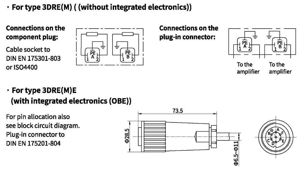
Electrical connections, plug-in connectors
Integrated electronics (OBE) of Types DREE and DREME
Function:
The integrated electronics is controlled via the two differential amplifier connections D and E.
The ramp generator generates from a command value step change (0 to 10 V or 10 to 0 V) a delayed increase or drop of the solenoid current.
Potentiometer R14 can be used to adjust the rise time, potentiometer R13 to adjust the drop time of the solenoid current.
The maximum ramp time of 5s is only possible over the full command value range. In the case of minor changes in the command value, the ramp time shortens accordingly.
The command value/solenoid current characteristic curve is adjusted to the valve by means of the characteristic curve generator so that non-linearities in the hydraulic system are compensated for and a linear command value/pressure characteristic curve is obtained.
The current regulator regulates the solenoid current independently of the solenoid coil resistance.
Potentiometer R30 can be used to change the gradient of the command value/current characteristic curve and hence the gradient of the command value/pressure characteristic curve of the proportional pressure control valve.
Potentiometer R43 serves for adjusting the biasing current. This setting should not be changed. If required, adjust the zero point of the command value/pressure characteristic curve on the valve seat.
A chopper amplifier forms the power stage of the electronics for controlling the proportional valve. It is pulsewidth-modulated with a clock frequency of 300 Hz.
The solenoid current can be measured at both measuring sockets MP1 and MP2. A voltage drop of 0.352V at the measuring resistor corresponds to a solenoid current of 1.6 A.
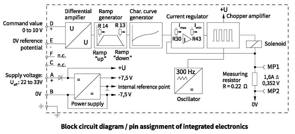
Integrated electronics (OBE) of Types DREE and DREME
Supply voltage
Power supply unit with rectifier.Single-phase rectification or three-phasecurrent bridge: \(U_{\text{eff}}\)=22 to 33VResidual ripple content on thepower supply unit : < 5 %Output current: \(I_{\text{eff}}\) = max. 1.4ASupply cable:– Recommended: 5-wire, 0.75 or 1 mm²with protective conductor and shield– Outer diameter 6.5 to 11 mm– Shield to 0 V supply voltage– Max. permissible length 100 m
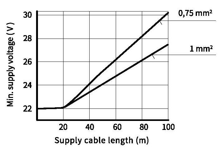
The minimum supply voltage of the power supply unit depends on the length of the supply cable (see diagram). In the case of lengths >50 m, a capacitor of 2200µ must be provided in the supply cable in the vicinity of valve.
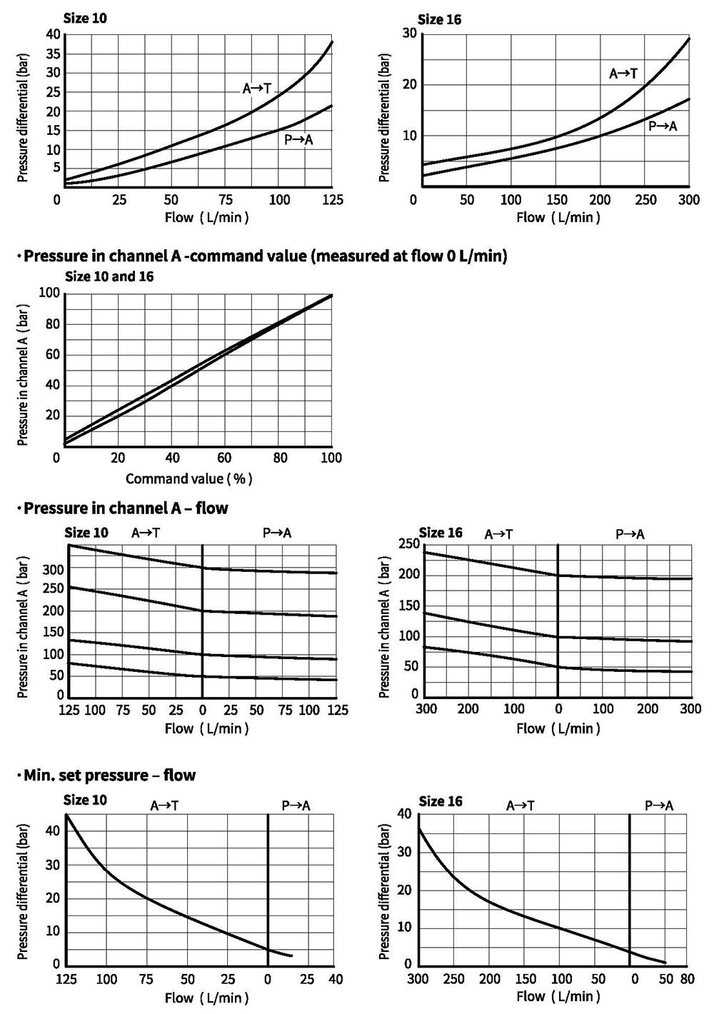
Characteristic curves (measured with HLP46, oil=40°C +5°C and p=100bar)
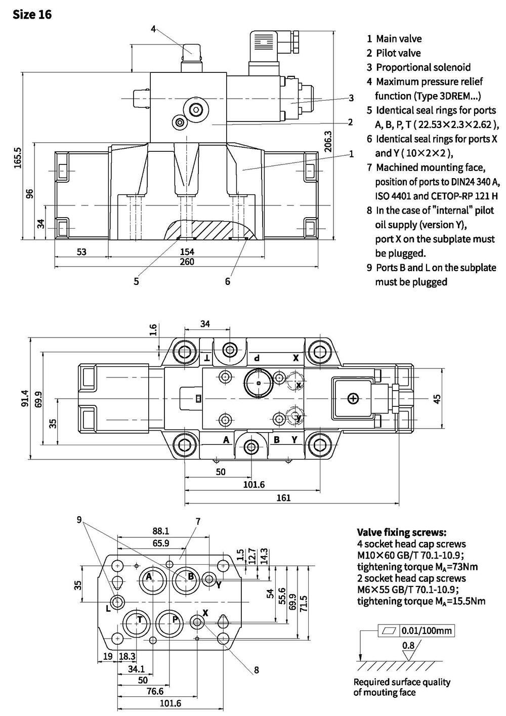
Unit dimensions
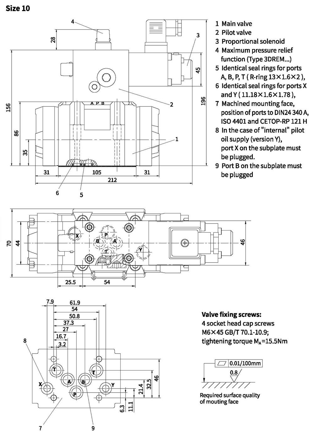
Unit dimensions
Pilot oil supply
Type 3DRE...-...XY
Pilot oil supply external
Pilot oil drain external
With this version, the pilot oil is supplied from a separate control circuit (external).
The pilot oil drain is not directed to the T-channel of the main valve,
but fed separately to the tank via port Y (external).
Type 3DRE...-.../...Y...
Pilot oil supply internal
Pilot oil drain external
With this version, the pilot oil is supplied from the P-channel of the main valve (internal).
The pilot oil drain is not directed to the T-channel of the main valve,
but fed separately to the tank via port Y (external).
Port X on the subplate must be plugged.