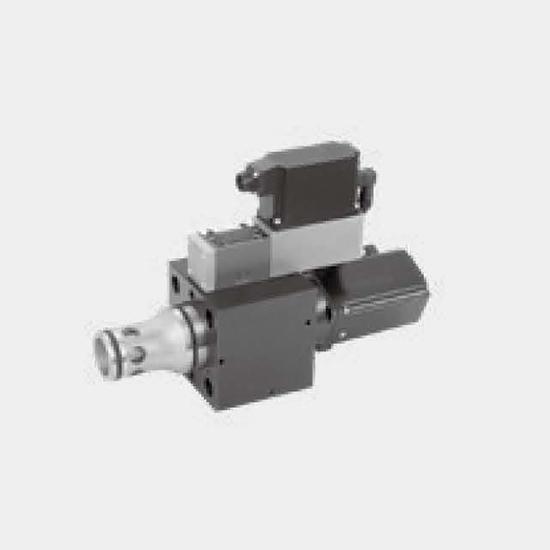
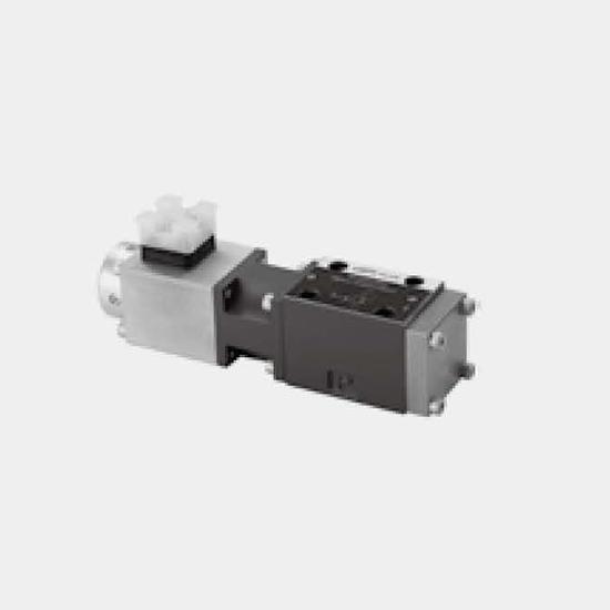
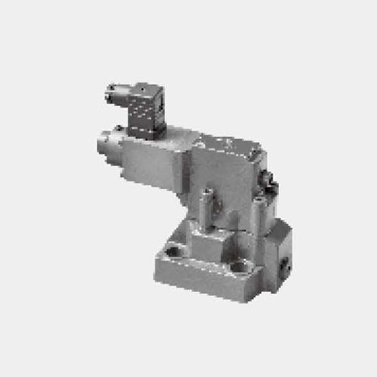
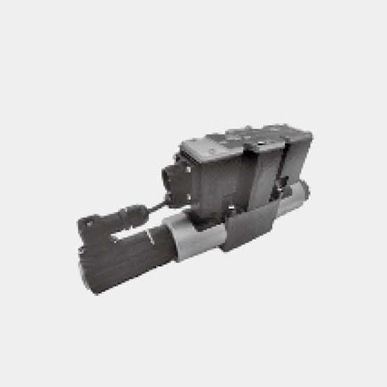
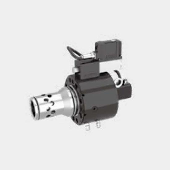
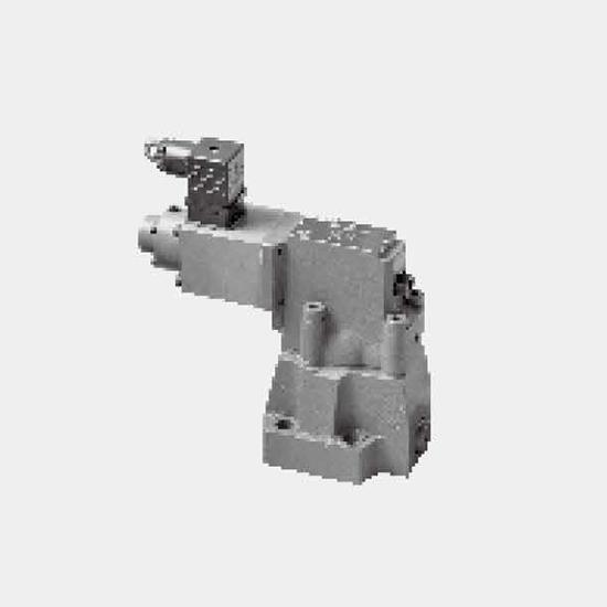
Function and configurationValves of type 2WRCE...-L1X/P... are 2-stage high-response valves.They control the quantity and direction of a flow and are mainly used in control loops.Set-up:They consist o...
Product Detail
Function and configuration
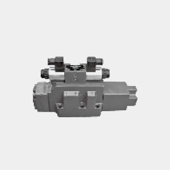
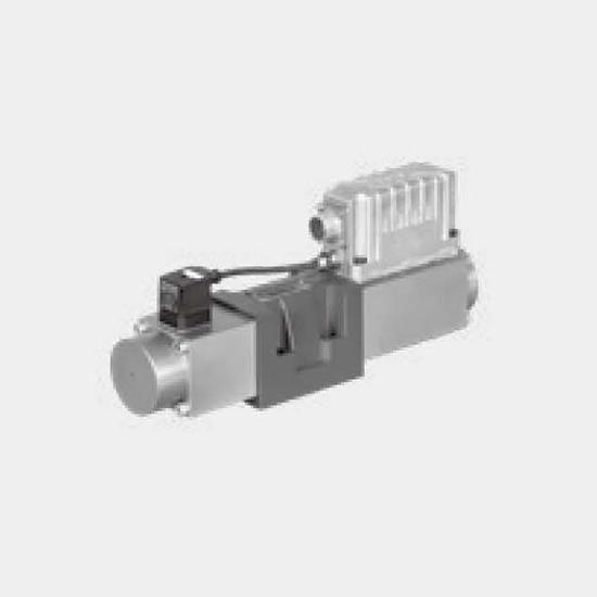
Valves of type 2WRCE...-L1X/P... are 2-stage high-response valves.
They control the quantity and direction of a flow and are mainly used in control loops.
Set-up:
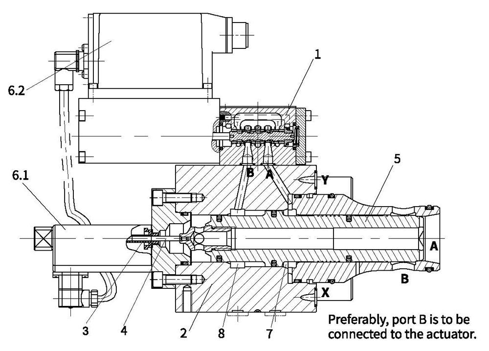
They consist of the following assemblies:
– The pilot control valve (1) as 1-stage proportional valve (pilot),
with a solenoid as electro-mechanical converters and a piston that is connected
to the integrated pilot electronics via electrical feedback (6.2).
– The second stage (2) for flow control.
– An inductive position transducer (3) the core (4) of which is attached to the piston (5)
of the second stage.
– Integrated LVDT electronics (6.1).
Type 2WRCE40...-L1X/P
Function
The integrated electronics (OBE) compares command and actual values and the solenoids of the pilot
control valve are actuated with a proportional current according to the control deviation.
The pilot control valve takes a proportionally controlled position and controls the flow in and out of the
control chambers A (7) and B (8) that actuate the main spool (5) through the closed valve control loop up
to 0 control deviation.
This means that the stroke of the main spool is regulated proportionally to the command value. It must
be noted that the flow also depends on the valve pressure drop.
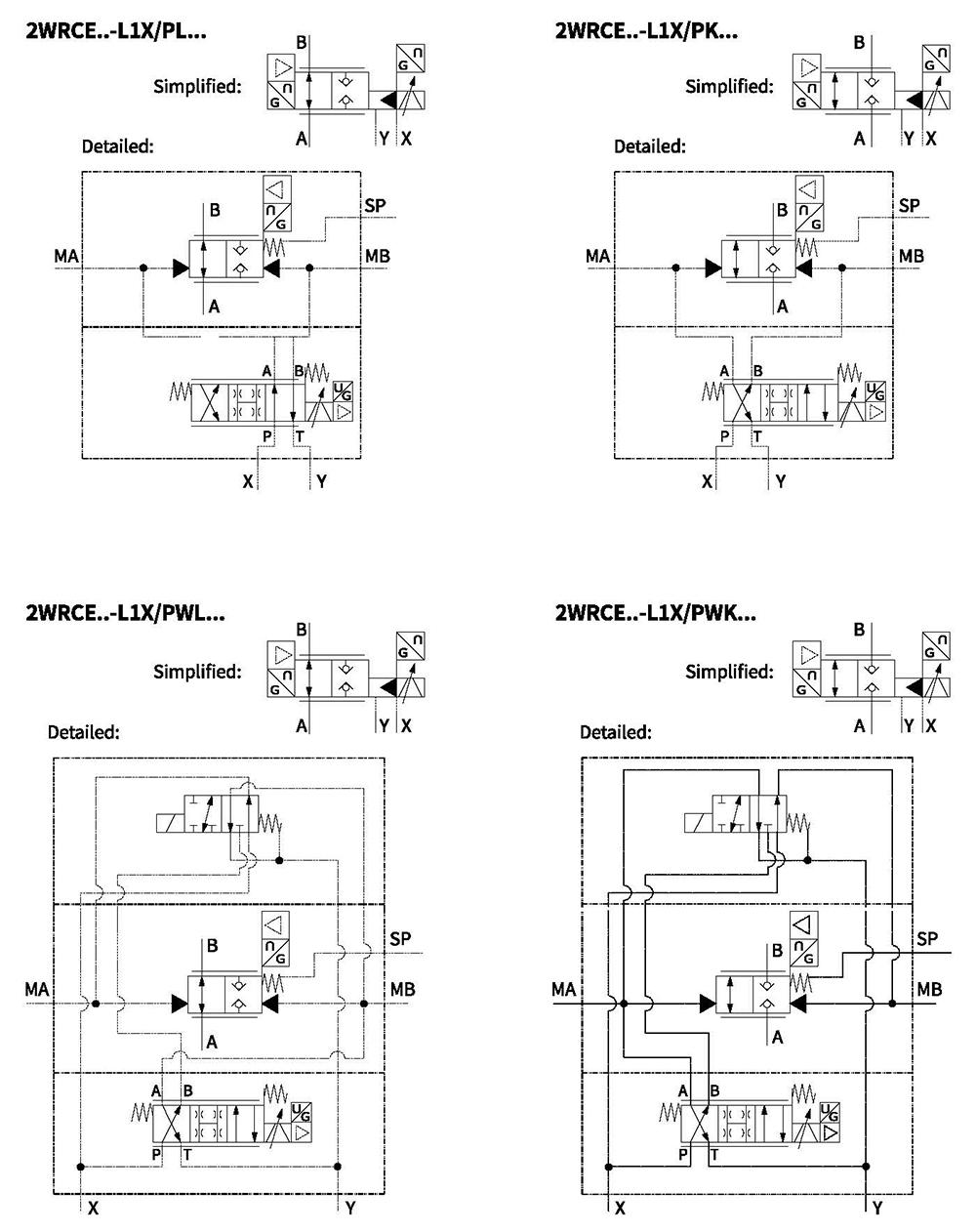
Symbols
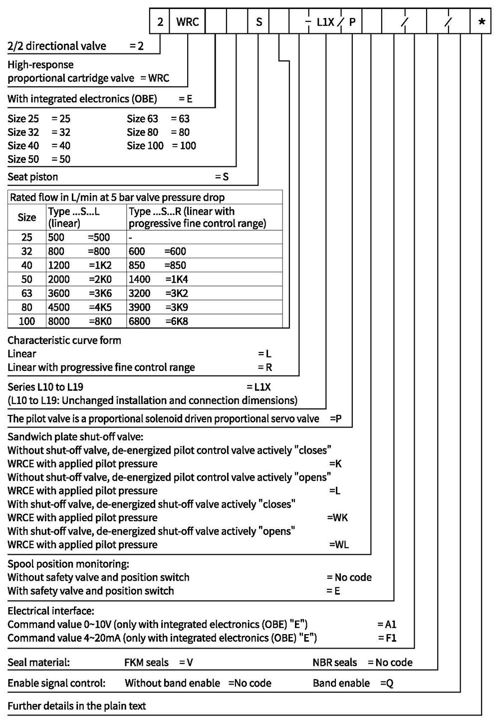
Ordering code
Technical data
| General | ||||||||
| Size | 25 | 32 | 40 | 50 | 63 | 80 | 100 | |
| Without shut-off valve ...../...K or.../...L Weight With shut-off valve ...../...WK or.../...WL... | kg | 8.5 | 11.2 | 17.3 | 24.6 | 47 | 74 | 110 |
| kg | 9.8 | 12.5 | 18.6 | 25.9 | 60 | 87 | 123 | |
| Size of the pilot control valve (pilot) | NG | 6 | ||||||
| Installation position | Any,preferably horizontal | |||||||
| Storage temperature range | ℃ | -20 to+80 | ||||||
| Ambient temperature range | ℃ | -20 to+50 | ||||||
Hydraulic (measured with HLP32,0oil=40℃±5℃)
| Maximum operating pressures | - Main stage ports A, B | bar | 350 | ||||||
| -Pilot control valve port X | bar | 315 | |||||||
| - Pilot control valve port Y | bar | 35 | |||||||
| Rated flow atΔp=5 bar | - Design...S...L(linear) | L/min | 500 | 800 | 1200 | 2000 | 3600 | 4500 | 8000 |
| - Design...S...R (linear with progressive fine control range) | - | 600 | 850 | 1400 | 3200 | 3900 | 6800 | ||
| Nominal flow of pilot valve at Δp=70 bar | L/min | 12 | 12 | 40 | 40 | 100 | 100 | 100 | |
| Leakage of pilot valve at P=100 bar | L/min | 0.3 | 0.3 | 0.7 | 0.7 | 1 | 1 | 1 | |
| Hydraulic fluid | Mineral oil (HL, HLP) to DIN 51524 | ||||||||
| Hydraulic fluid temperature range | ℃ | -20 to +80;preferably +40 to+50 | |||||||
| Viscosity range | m㎡/s | 20 to 380; preferably 30 to 45 | |||||||
| Max. admissible degree of contamination of the hydraulic fluid, cleanliness class according to ISO 4406 (c) | Class 20/18/15 | ||||||||
| Hysteresis | % | ≤0.2 | |||||||
| Range of inversion | % | ≤0.1 | |||||||
| Response sensitivity | % | ≤0.1 | |||||||
| Response time 0~ 100% step signal | ms | 14 | 15 | 18 | 20 | 24 | 30 | 50 | |
| Electric | |||
| Voltage type | Direct voltage | ||
| Type of signal | Analog | ||
| Opening point caibration | % | ≤1 | |
| Zero shift upon change of: | -Hydraulic fluid temperature | %/10K | ≤0.3 |
| - Pilot pressure in X | %/ 100 bar | ≤0.7 | |
| - Return flow pressure in Y | %/bar | ≤0.3 | |
| Protection class of the valve according to EN60529 | IP65 with mating connector mounted and locked | ||
Nominal command value range for 2WRCE:
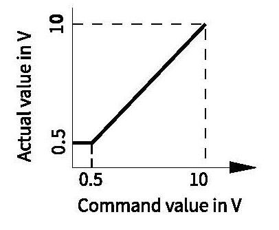
0 to +10 V ≜ 0 to 100%
In the command value range of 0 to 0.5 V, the actual value remains constant at 0.5 V.
In case of a slow command value modification from 0.5 V to +10 V, the actual value follows the command value within ±0.15 V.
Integrated electronics (OBE)
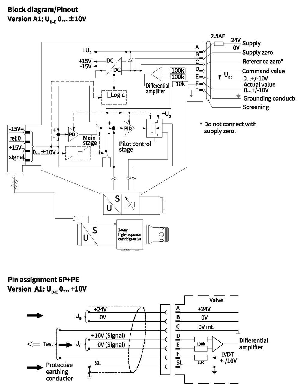
Integrated electronics (OBE)
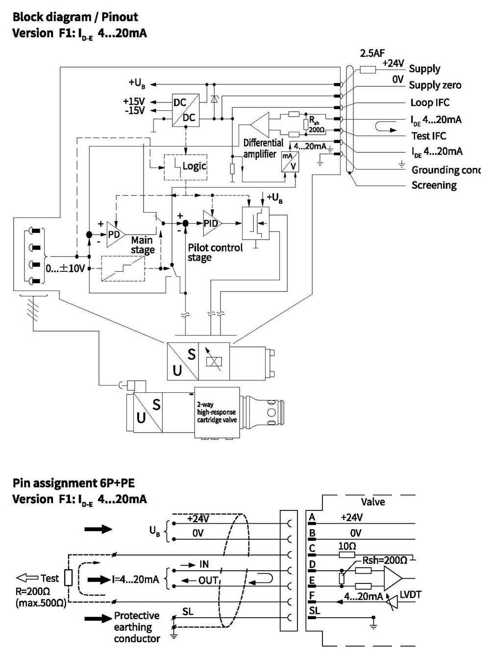
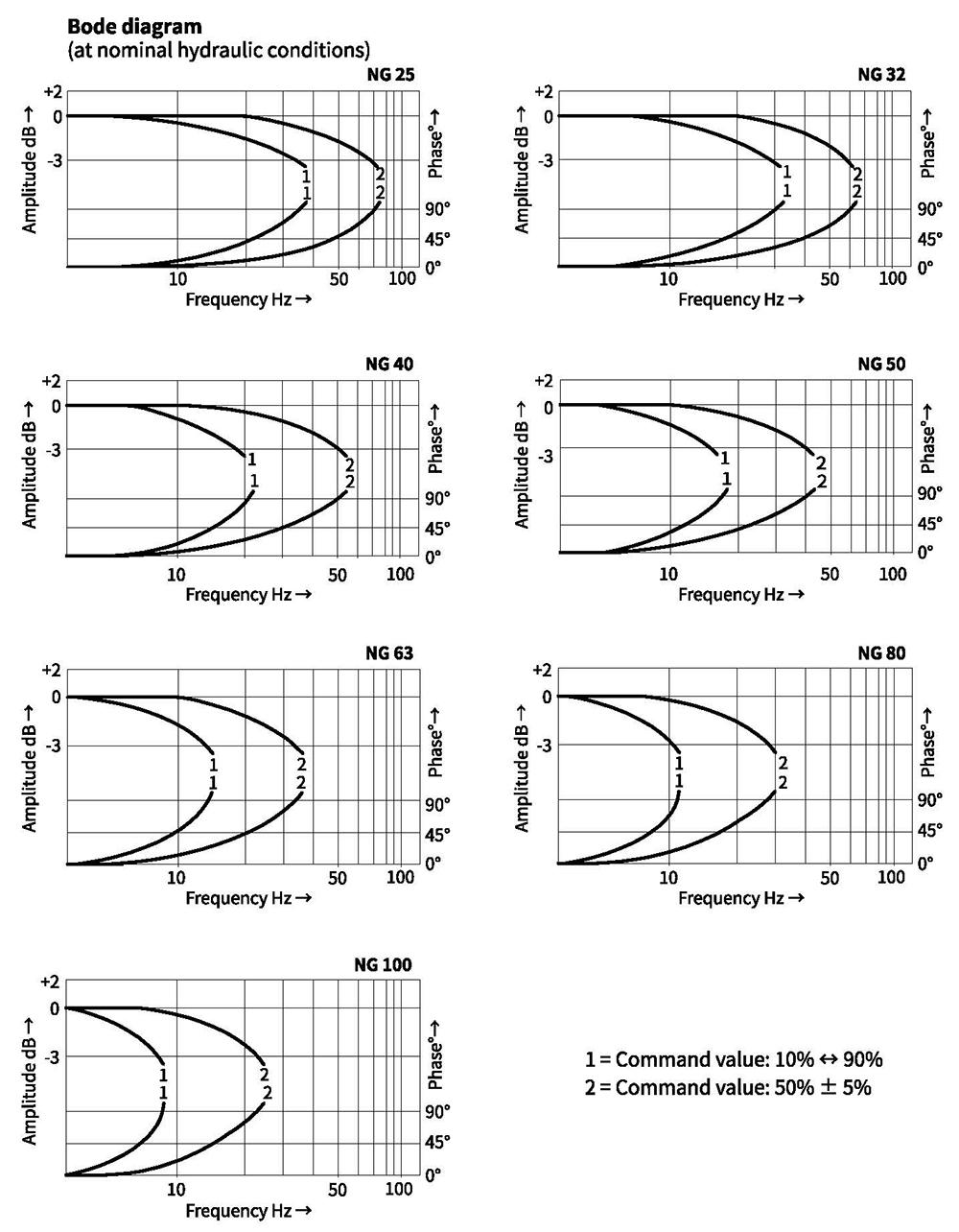
Characteristic curves(measured with HLP46, oil=50°C, AP=5bar)
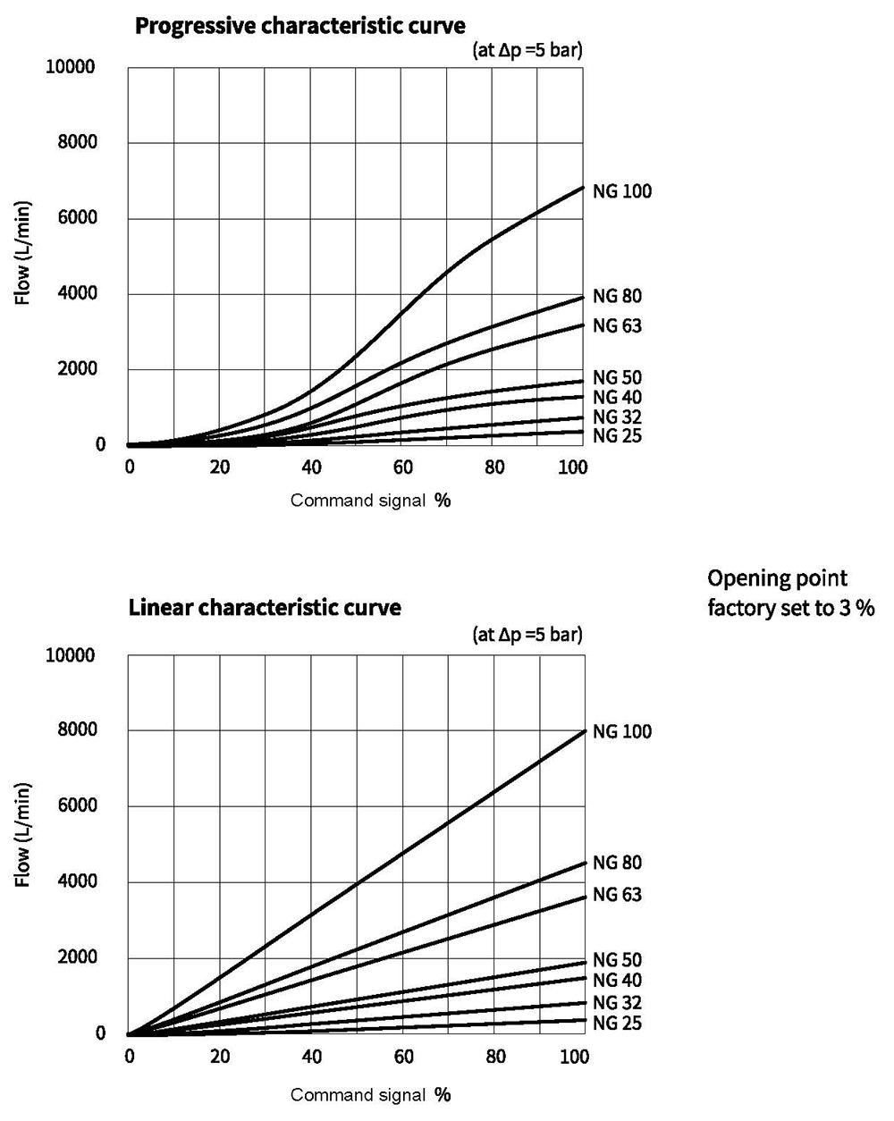
Characteristic curves (measured with HLP46, oil =50°C, AP=5bar)
Unit dimensions
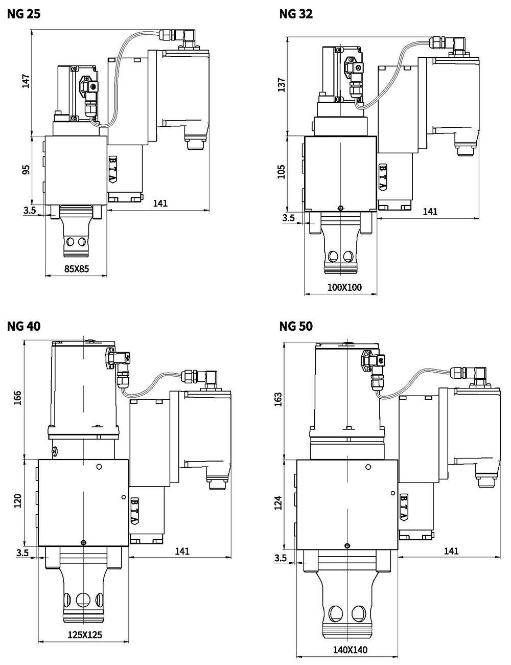
| Size | Fastening bolts class 12.9 | Tightening torque |
| 25 | 4-M12x100 | 125 Nm |
| 32 | 4-M16x60 | 300 Nm |
| Size | Fastening bolts class 12.9 | Tightening torque |
| 40 | 4-M20x70 | 600 Nm |
| 50 | 4-M20x80 | 600 Nm |
Unit dimensions
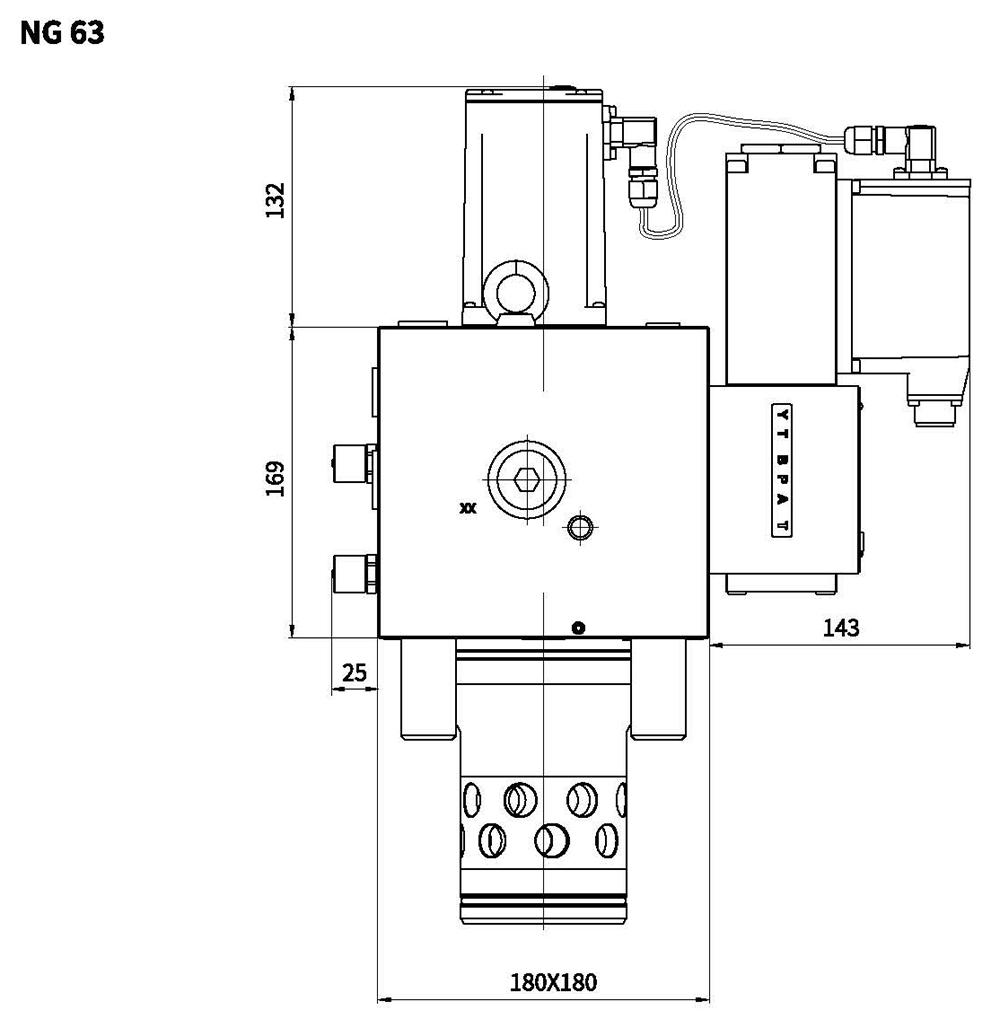
| Size | Fastening bolts class 12.9 | Tightening torque |
| 63 | 4-M30x160 | 1775 Nm |
Unit dimensions
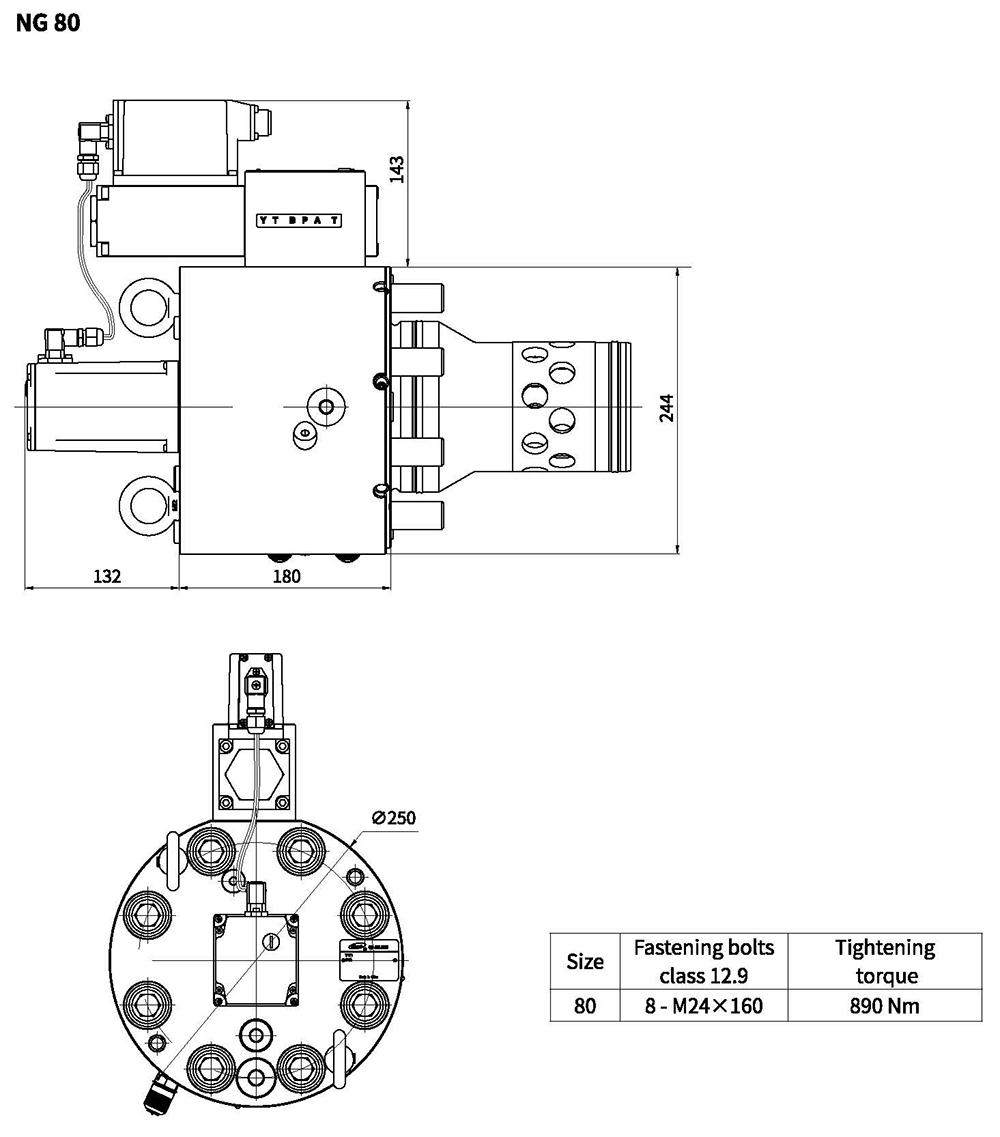
Unit dimensions
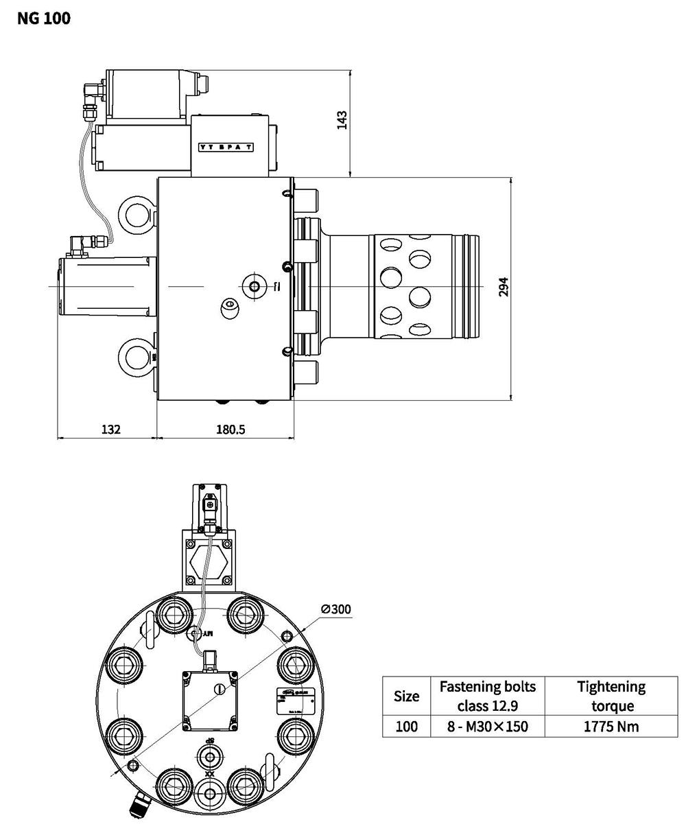 11
Installation dimensions according to DIN ISO 7368
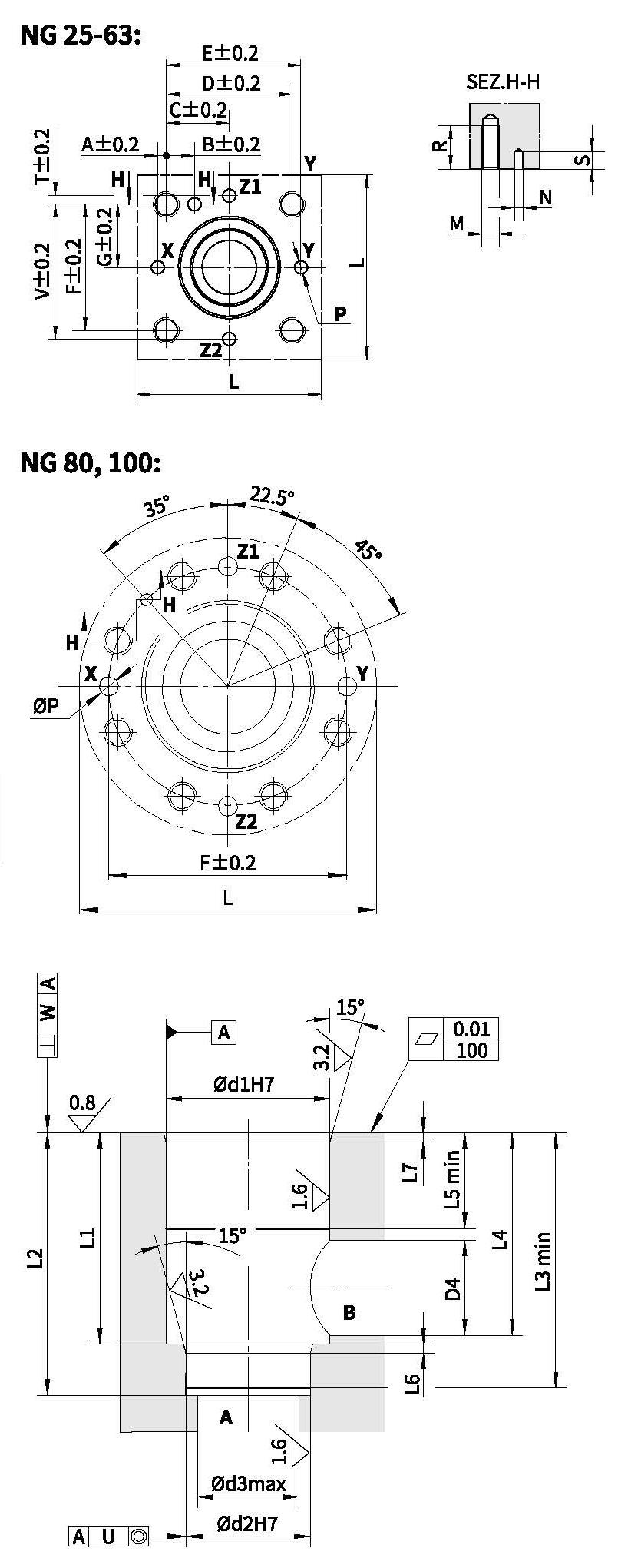
| Size | 25 | 32 | 40 | 50 | 63 | 80 | 100 |
| A | 4 | 6 | 7.5 | 8 | 12.5 | - | - |
| B | 13 | 18 | 19.5 | 20 | 24.5 | - | - |
| C | 29 | 35 | 42.5 | 50 | 62.5 | - | - |
| D | 58 | 70 | 85 | 100 | 125 | - | - |
| E | 62 | 76 | 92.5 | 108 | 137.5 | - | - |
| F | 58 | 70 | 85 | 100 | 125 | 200 | 245 |
| G | 29 | 35 | 42.5 | 50 | 62.5 | - | - |
| L min | 85 | 102 | 125 | 140 | 180 | 250 | 300 |
| M | M12 | M16 | M20 | M20 | M30 | M24 | M30 |
| ØN | 6 | 6 | 6 | 8 | 8 | 10 | 10 |
| ØP max | 6 | 8 | 10 | 10 | 12 | 16 | 20 |
| R | 30 | 38 | 46 | 46 | 66 | 50 | 66 |
| Smax | 8 | 8 | 8 | 8 | 8 | 8 | 10 |
| T | 4 | 6 | 7.5 | 8 | 12.5 | - | - |
| V | 62 | 76 | 92.5 | 108 | 137.5 | - | - |
| Ød1 | 45 | 60 | 75 | 90 | 120 | 145 | 180 |
| Ød2 | 34 | 45 | 55 | 68 | 90 | 110 | 135 |
| Ød3 max | 25 | 32 | 40 | 50 | 63 | 80 | 100 |
| Ød4 max | 27 | 38.5 | 54.5 | 62.5 | 87 | 100 | 120 |
| L1 | 58+0.1 0 | 70 +0.1 0 | 87 +0.1 0 | 100 +0.1 0 | +0.1 130 - 0 | 175 +0.2 0 | 210 +0.2 0 |
| L2 | 72 +0.1 0 | 85+0.1 0 | 105 0 +0.1 0 | 122 +0.1 | 155 +0.1 0 | 205 +0.2 0 | 245 +0.2 0 |
| L3 | 70 | 83 | 102 | 117 | 150 | 200 | 239 |
| L4 | 57 | 68.5 | 84.5 | 97.5 | 127 | 170.5 | 205.5 |
| L5 | 30 | 30 | 30 | 35 | 40 | 40 | 50 |
| L6 | 2.5 | 2.5 | 3 | 3 | 4 | 5 | 5 |
| L7 | 2.5 | 2.5 | 3 | 3 | 4 | 5 | 5 |
| U | 0.03 | 0.03 | 0.05 | 0.05 | 0.05 | 0.05 | 0.05 |
| W | 0.05 | 0.1 | 0.1 | 0.1 | 0.2 | 0.2 | 0.2 |