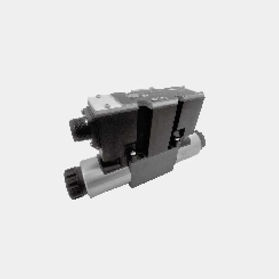
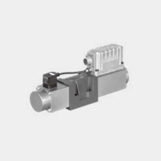
Function and configurationPilot valve type 3DREP 6...The pilot valve is a proportional solenoid operated 3-way pressure reducing valve. It is used to convert an electrical input signal into a proporti...
Product Detail
Function and configuration
Pilot valve type 3DREP 6...
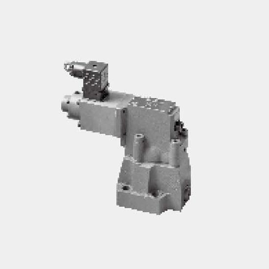
The pilot valve is a proportional solenoid operated 3-way pressure reducing valve. It is used to convert an electrical input signal into a proportional pressure output signal and is used on all 4WRZ... valves.
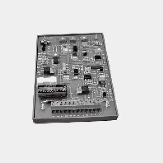
The proportional solenoids are controllable DC wet pin solenoids with central thread and detachable coil. The solenoid is optionally controlled by external electronics (type WRZ...) or integrated electronics (type WRZE...).
Design:
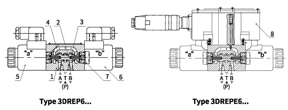
The valve basically consists of:
Housing (1)
Control spool (2) with pressure measuring spools (3 and 4)
Solenoids (5 and 6) with central thread
Optionally with integrated electronics (8)
Work principle
When the solenoids (5 and 6) are in the de-energized condition, the control spool (2) is held by compression springs in the central position
Direct operation of the control spool (2) by energizing a proportional solenoid, e.g. energization of solenoid "a" (5). Pressure measuring spool (3) and control spool (2) are shifted to the left in proportion to the electrical input signal; Connection from P to B and A to T through the orifice-like cross sections with progressive flow characteristics; De-energization of the solenoid (5), control spool (2) is returned to the central position by the compression spring, In the central position, ports A and B are open to T, i.e. the hydraulic fluid can flow to the tank without any restrictions.
Manual override, optional, with the help of it, the control spool (2) can be moved without requiring the energization of the solenoid.
Notes:
Type 3DREP 6: Draining of the tank line must be prevented. In the case of a corresponding installation situation, a pre-load valve is to be installed (pre-load pressure approx. 2 bar).
Pilot valve with two spool positions
(Type 3DREP 6...B...)
In principle, the function of this valve version corresponds to that of the valve with three spool positions.
However, this 2-position valve is provided with solenoid "a" (5) only. Instead of the 2nd proportional solenoid, a plug screw (7) is fitted.
Function and configuration
Pilot operated proportional directional valves
Type 4WRZ...
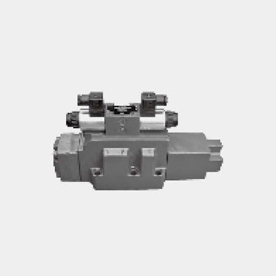
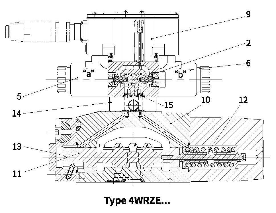
Valves of type 4WRZ... are pilot operated 4-way directional valves with operation by proportional solenoids. They control the direction and magnitude of a flow.
Design:
The valves basically consist of:
– A pilot valve (9) with proportional solenoids (5 and 6), control spool (2) and orifice plugs (15)
– A main valve (10) with main spool (11) and centering spring (12)
Work principle
– When the solenoids (5 and 6) are de-energised, the main spool (11) is held by centering springs (12) in the central position.
– Operation of the main spool (11) through the pilot valve (9), the main spool is moved proportionally, depending on the spool position, flow from P to A and B to T(R) or P to B and A to T(R).
e.g. by energising solenoid "b" (6), the control spool (2) is shifted to the right, pilot oil is fed through the pilot valve (9) into the pressure chamber (13) and moves the main spool (11) in proportion to the electrical input signal; Connection from P to A and B to T through orifice-like cross-sections with progressive flow characteristics.
De-energization of the solenoid (6), the control spool (2) and main spool (11) are returned to the central position.
– Pilot oil supply to the pilot valve internally via port P or externally via port X.
– With the help of an optional manual override the control spool (2) can be moved without requiring the energization of the solenoid.
Notes:
Type WRH: The pilot pressure in the main valve must not exceed 25 bar.
Type WRZ: For system pressures above 100bar the type D3 pilot pressure reducing module(14) must be fitted between pilot valve (9) and main valve (10).
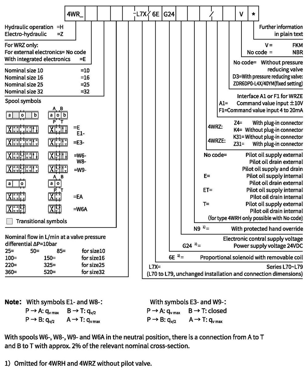
Ordering code
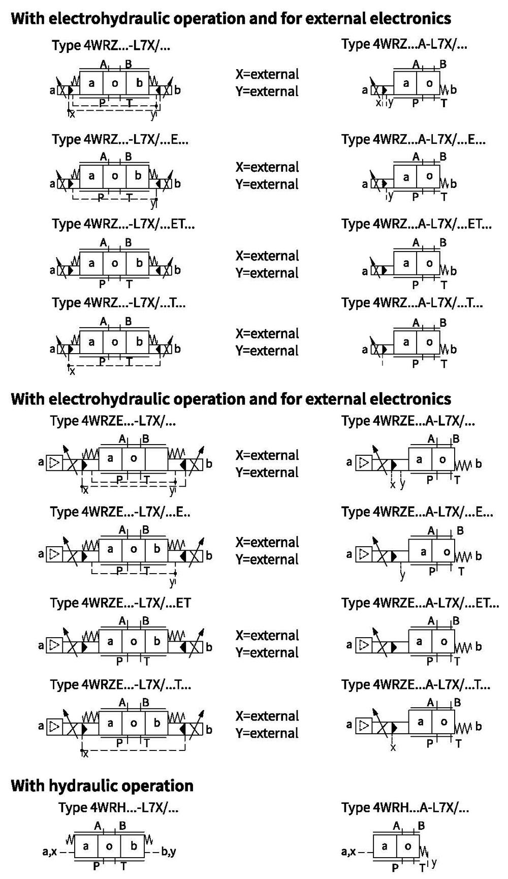
Symbols(simplified)
Technical data
| General | ||||
| Valve type | WRZ | WRZE | ||
| Installation | optional, preferably horizontal | |||
| Storage temperature range | ℃ | -20 to+80 | ||
| Ambient temperature range | ℃ | -20 to+70 | -20 to+50 | |
| Weight | NG10 | kg | 7.8 | 8.0 |
| NG16 | kg | 13.4 | 13.6 | |
| NG25 | kg | 18.2 | 18.4 | |
| NG32 | kg | 42.2 | 42.4 | |
| Hydraulic (measured with HLPAG.p=100bar : 40℃±5℃) 】 | ||||||||
| Nominal size | 10 | 16 | 25 | 32 | ||||
| Operating pressure | -Pilot valve | External pilot oil supply | bar | 30 to 100 bar | ||||
| Internal pilot oil supply | bar | 100 to 350 with "D3"only | ||||||
| -Main valve | bar | up to 315 | up to 350 | up to 350 | up to 350 | |||
| Return flow pressure | -Port T (port R) (external pilot oil drain) | bar | up to 315 | up to 250 | up to 250 | up to 150 | ||
| -Port T(internal pilot oil drain) | bar | up to 30 | up to 30 | up to 30 | up to 30 | |||
| -Port Y | bar | up to 30 | up to 30 | up to 30 | up to 30 | |||
| Pilot oil volume input signal 0-100% | cm3 | 1.7 | 4.6 | 10 | 26.5 | |||
| Pilot oil flow in port X and Y with a stepped input signal 0-100% | L/min | 3.5 | 5.5 | 7 | 15.9 | |||
| Flow of the main valve | L/min | up to 170 | up to 460 | up to 870 | up to 1600 | |||
| Hydraulic fluid | Mineral oil (HL, HLP) to DIN 51524 Further fluids on enquiry! | |||||||
| Hydraulic fluid temperature range | ℃ | -20 to +80 (preferably +40 to +50) | ||||||
| Viscosity range | m㎡/s | 20 to 380 (preferably 30 to 46) | ||||||
| Degree of contamination | Maximum permissible degree of contamination of the pressure fluid is to NAS 1638 or ISO 4406(c) | A filter with a minimum retention rate of βx ≥ 75 is recommended | ||||||
| - Pilot valve | NAS 1638 class 7 | x=5 | ||||||
| -Main valve | NAS 1638 class 9 | x=15 | ||||||
| Hysteresis | % | ≤6 | ||||||
Electrical
| Valve type | WRZ | WRZE | ||
| Type of protection of the valve to EN 60529 | IP65 with cable socket mounted and locked | |||
| Voltage type | DC | |||
| Command value overlap | % | 15 | ||
| Max.current | A | 1.5 | 2.5 | |
| Solenoid coil resisance | Cold value at 20℃ | Ω | 4.8 | 2 |
| Max.warm value | Ω | 7.2 | 3 | |
| Duty | % | 100 | ||
| Coil temperature | ℃ | up to 150 | ||
| Valve protection to EN 60529 | IP65 with mounted and fixed plug-in connector | |||
Control electronics
| External amplifier for type WRZ | VT-VSPA2-1-L2X/... | ||
| Command value signal | -Voltage input "A1" | V | ±10 |
| -Current input "F1" | mA | 4 to 20 | |
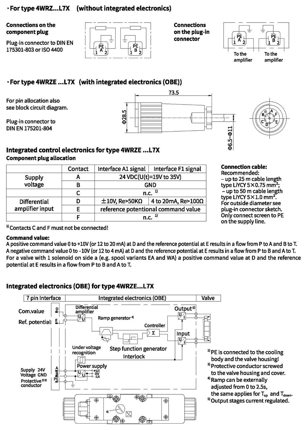
Electrical connections, plug-in connectors
Characteristic curves (measured with spools "E, W6, EA, W6A" and HLP46, oil=40°C 15°C, P=100bar)
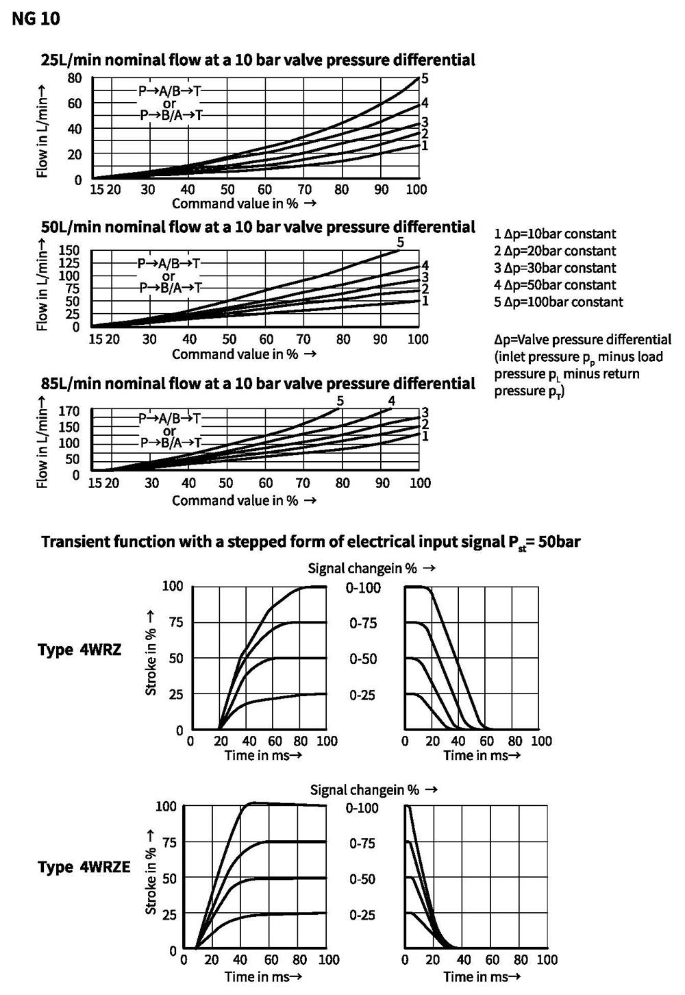
Characteristic curves (measured with spools "E, W6-, EA, W6A" and HLP46, oil=40°C ±5°C, P=100bar)
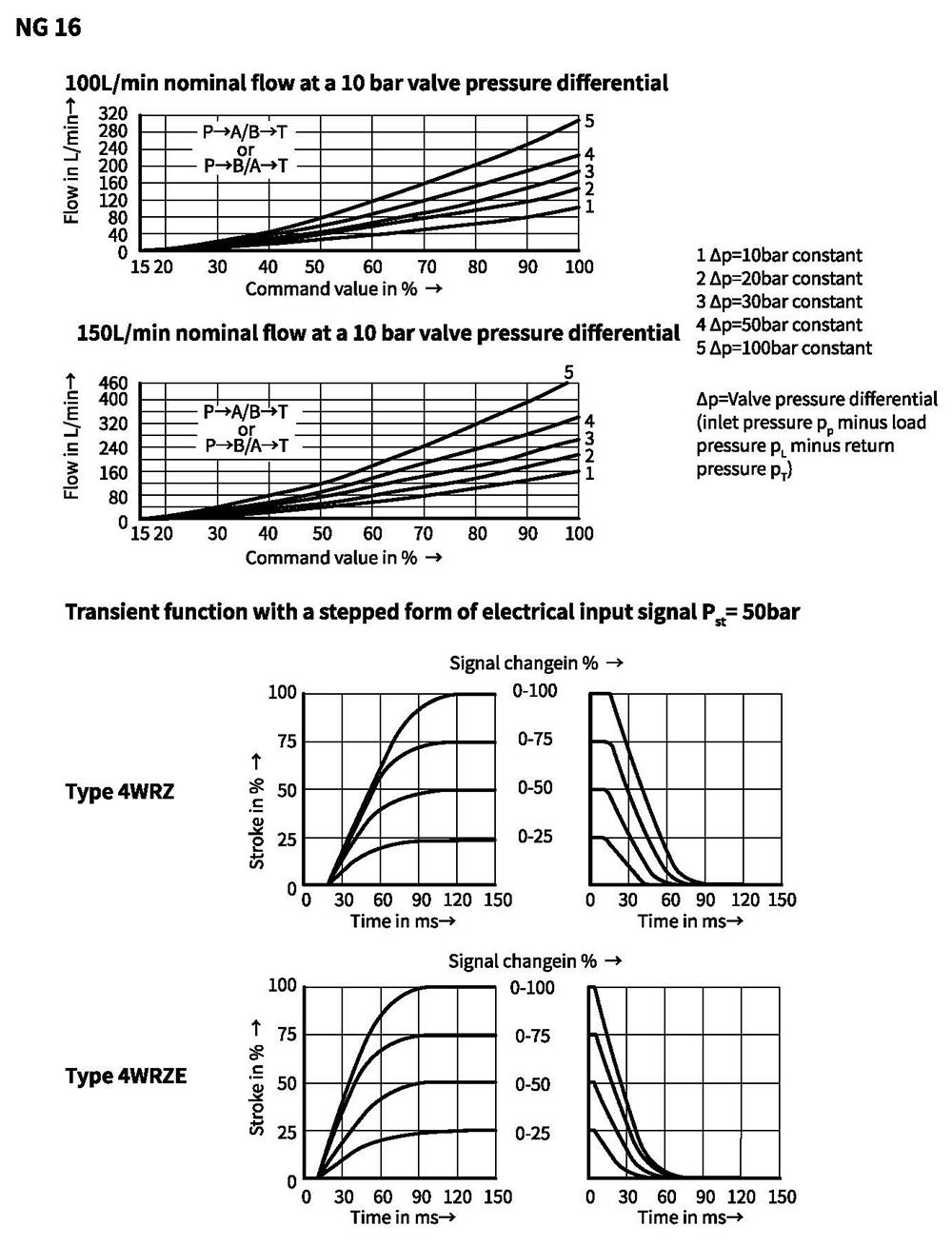
Characteristic curves (measured with spools "E, W6-, EA, W6A" and HLP46, oil=40°C +5°C, P=100bar)
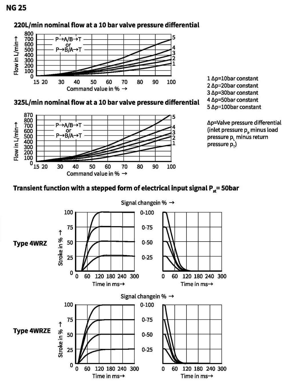
Characteristic curves (measured with spools "E, W6, EA, W6A" and HLP46, oil=40°C +5°C, P=100bar)
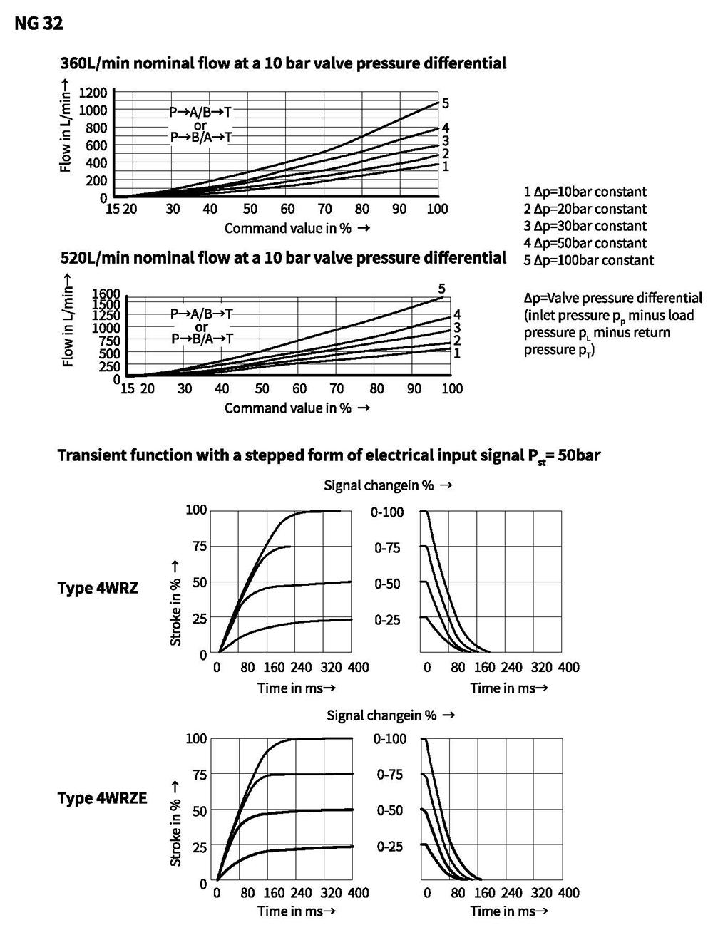
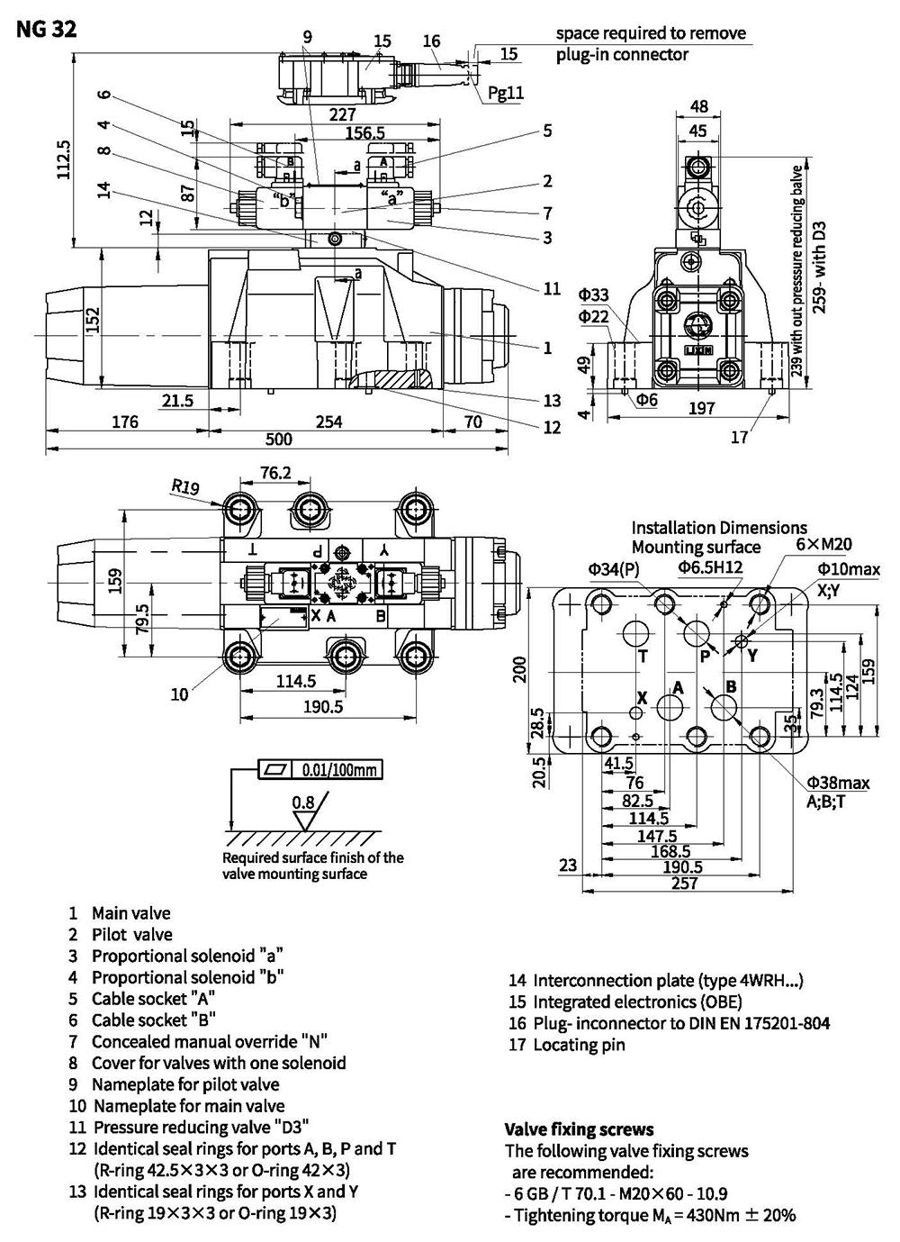
Unit dimensions
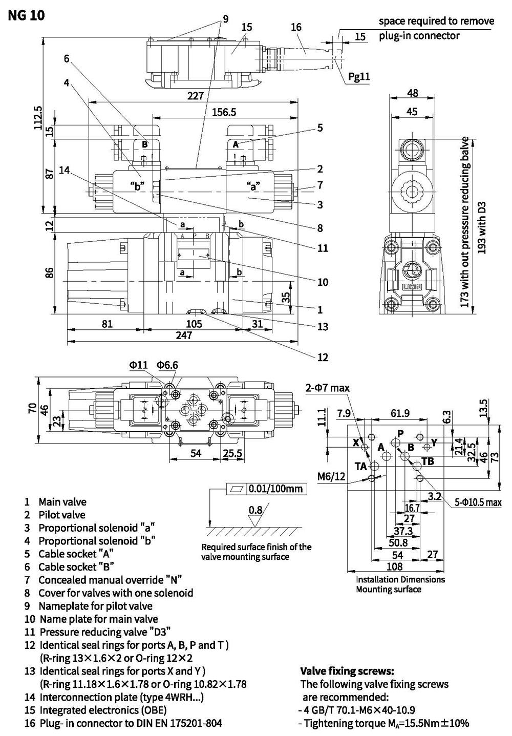
Unit dimensions
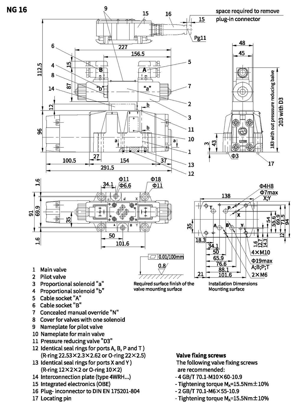
Unit dimensions
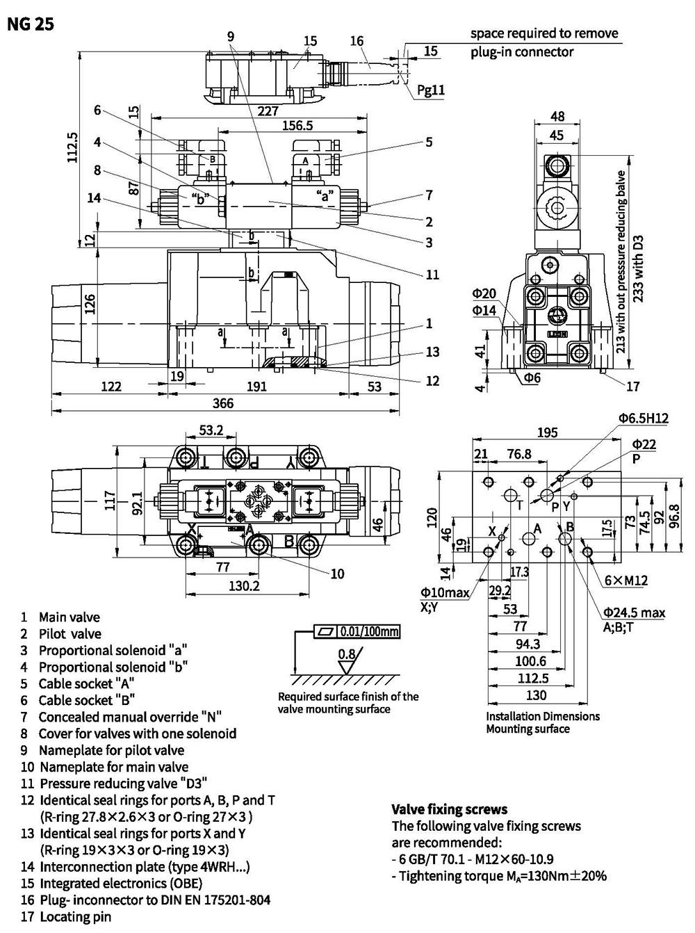
Unit dimensions