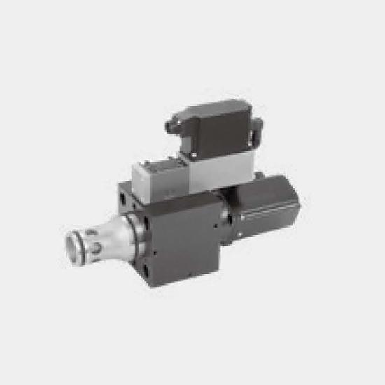
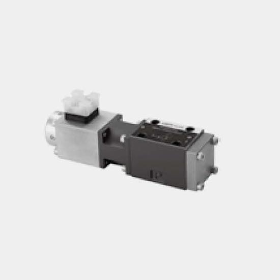
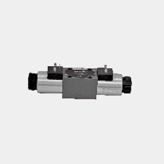
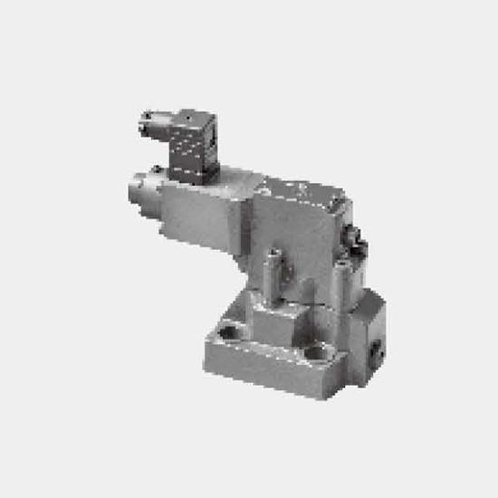
Function and configurationThe 4WRPE10...-L3X/G24K31/... type is a with electrical position feedback and integrated electronics (OBE).The valves basically consists of the housing (1), spool (2) with co...
Product Detail
Function and configuration
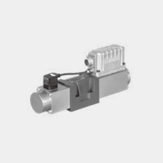
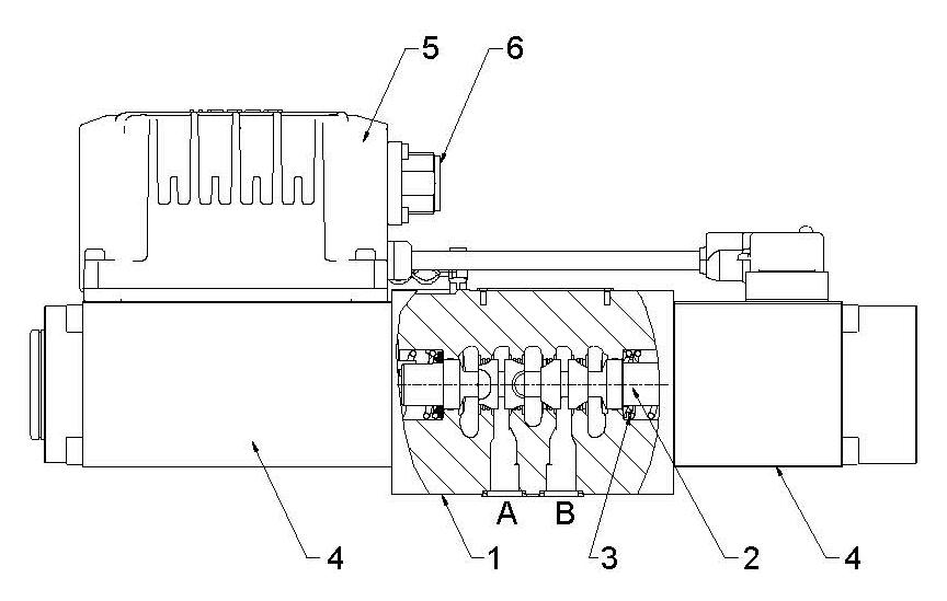
The 4WRPE10...-L3X/G24K31/... type is a with electrical position feedback and integrated electronics (OBE).
The valves basically consists of the housing (1), spool (2) with compression springs (3), control solenoid with and without position transducer (4) and integrated control electronics (OBE) (5).
The specified command value is compared with the actual position value in the integrated electronics (OBE). In the event of a control deviation, the stroke solenoid is activated, which adjusts the control spool against the spring due to the change in the magnetic force.
Stroke/control spool cross-section is controlled proportionally to the command value. In case of a command value presetting of 0V, the electronics adjusts the control spool against the spring to central position.
Type 4WRPE10...-L3X
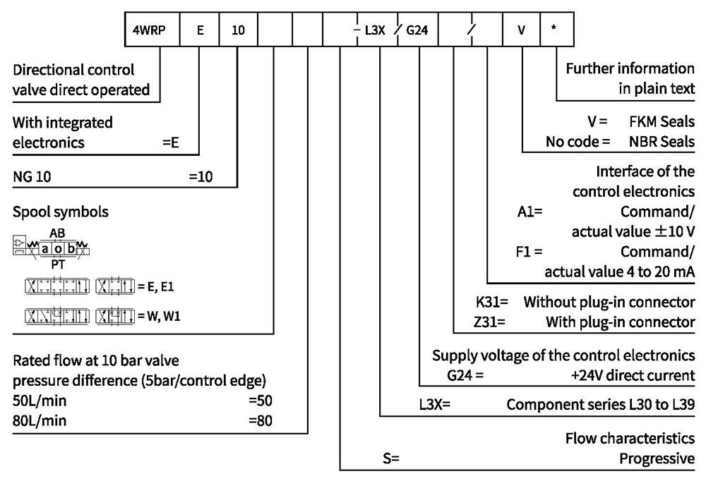
Ordering code
Technical data
| General | ||
| Design | Spool valve,directly operated, without sleeve | |
| Actuation | Proportional solenoid with position control, OBE | |
| Connection type | Plate port, porting pattern (ISO 4401-05-04-0-05) | |
| Installation position | Any | |
| Ambient temperature range | ℃ | -20...+60 |
| Weight | Kg | 7.8 |
| Maximum vibration resistance (test condition) | Max. 25 g, space vibration test in all directions(24h) | |
| Hydraulic (measured with HLP 46, ℃±5℃) 9oil=40 | ||||
| Viscosity range | Hydraulic oil according to DIN 51524...535 | |||
| Viscosity range | Recommended | m㎡ n2/s | 20···100 | |
| Max.admissible | m㎡/s | 10···800 | ||
| Hydraulic fluid temperature range | ℃ | -20 to+70 | ||
| Max.admissible degree of contamination of the hydraulic fluid,cleanliness class according to ISO 4406 (c) | Class 18/16/13 ") | |||
| Rated flow (Δp = 5 bar per edge), 2) | L/min | 50 | 80 | |
| Maximum operating pressure | bar | Port P,A,B:350 | ||
| Maximum pressure | bar | Port T:200 | ||
| Static/Dynamic | |||
| Hysteresis | % | ≤0.3 | |
| Range of inversion | % | <0.05 | |
| Manufacturing tolerance qvmax | % | 10 | |
| Actuating time | for signal step 100% | ms | 40 |
| for signal step 10% | ms | 10 | |
| Temperature drift (temperature range 20 | °℃...80℃) | Zero shift <0.2 | |
| Response sensitivity | % | <0.05 | |
1) The cleanliness classes stated for the components need to be maintained in hydraulic systems. Effective filtration prevents faults and at the same time increases the life cycle of the components.
2) Flow with deviating Δp:Qa=Qnom
Technical data
| Electric, control electronics integrated in the valve | |||
| Relative duty cycle | % | 100ED | |
| Protection class | IP 65 (with mating connector mounted and locked) DIN 40050 and IEC 14434/5 | ||
| Connection | Mating connector 6P+PE, DIN 43563 | ||
| Supply voltage Terminal A Terminal B: OV | 24VDCnom | ||
| min.21VDC/max.40VDC | |||
| Ripple max.2VDC | |||
| Power consumption | 60 VA max. | ||
| Fuse protection, external | AF | 2.5 | |
| Input, version "A1" Terminal D (U) Terminal E | Differential amplifier, R1=100kΩ | ||
| ±10V | |||
| OV | |||
| Input, version "F1" Terminal D (ID-E) Terminal E (ID-E) | Load, Rsh=200Ω | ||
| 4...12...20mA | |||
| Current loop ID-return | |||
| Max.differential input voltage at 0 V | D→B E→B | max.18V DC | |
| Test signal, version "A1" Terminal F (UTest) Terminal C | LVDT | ||
| ±10V | |||
| Reference 0 V | |||
| Test signal,version "F1" TerminalF(IFc) Terminal C(IFc) | LVDT | ||
| 4...20 mA output | |||
| Current loop lF-c feedback | |||
| Protective conductor and screen | See pin assignment | ||
| Recommended cable | See pin assignment Up to 20m 7x0.75m㎡ Up to 40m 7x1m㎡ | ||
| Calibration | Calibrated at the factory, see characteristic curve | ||
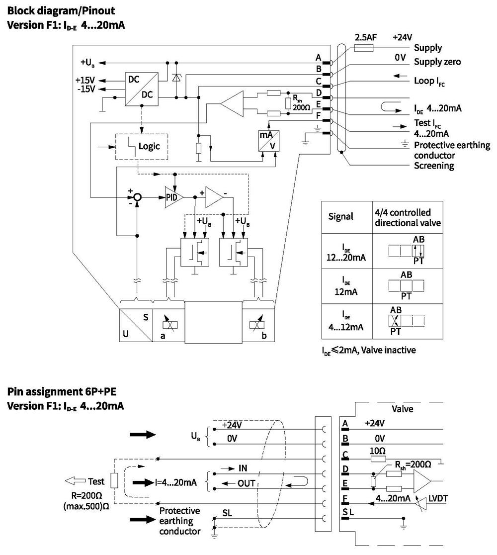
Integrated electronics
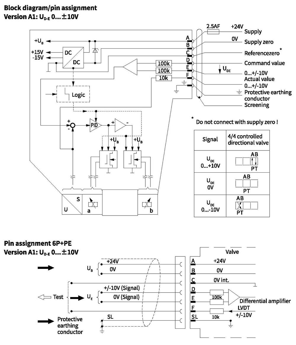
Integrated electronics
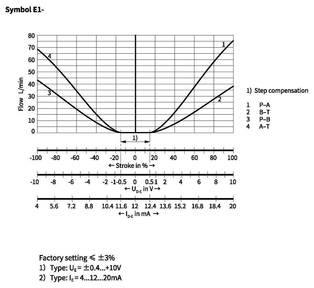
Characteristic curves(measured with HLP46, oil=40°c 5°c, Ap=5 bar/control edge)
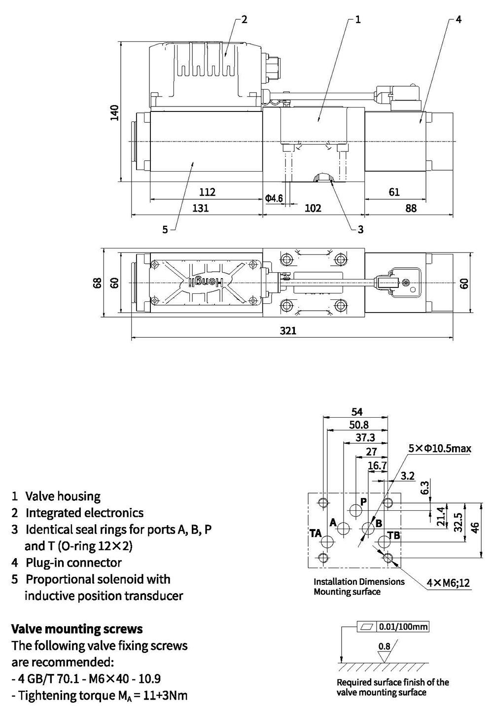
Unit dimensions