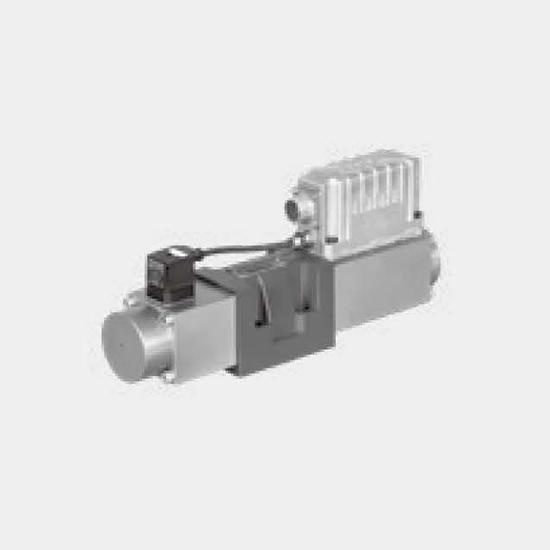
Function and configurationThe 4WRPEH type high-response valve is a pilot-operated directional control valve with electrical position feedback and integrated electronics (OBE).The valves basically cons...
Product Detail
Function and configuration
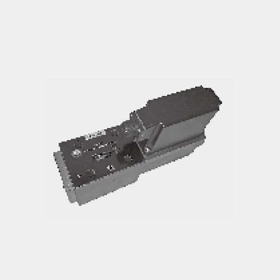
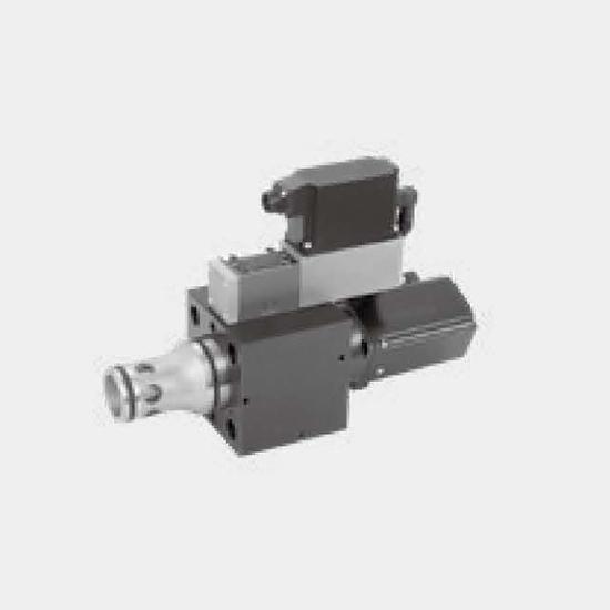
The 4WRPEH type high-response valve is a pilot-operated directional control valve with electrical position feedback and integrated electronics (OBE).
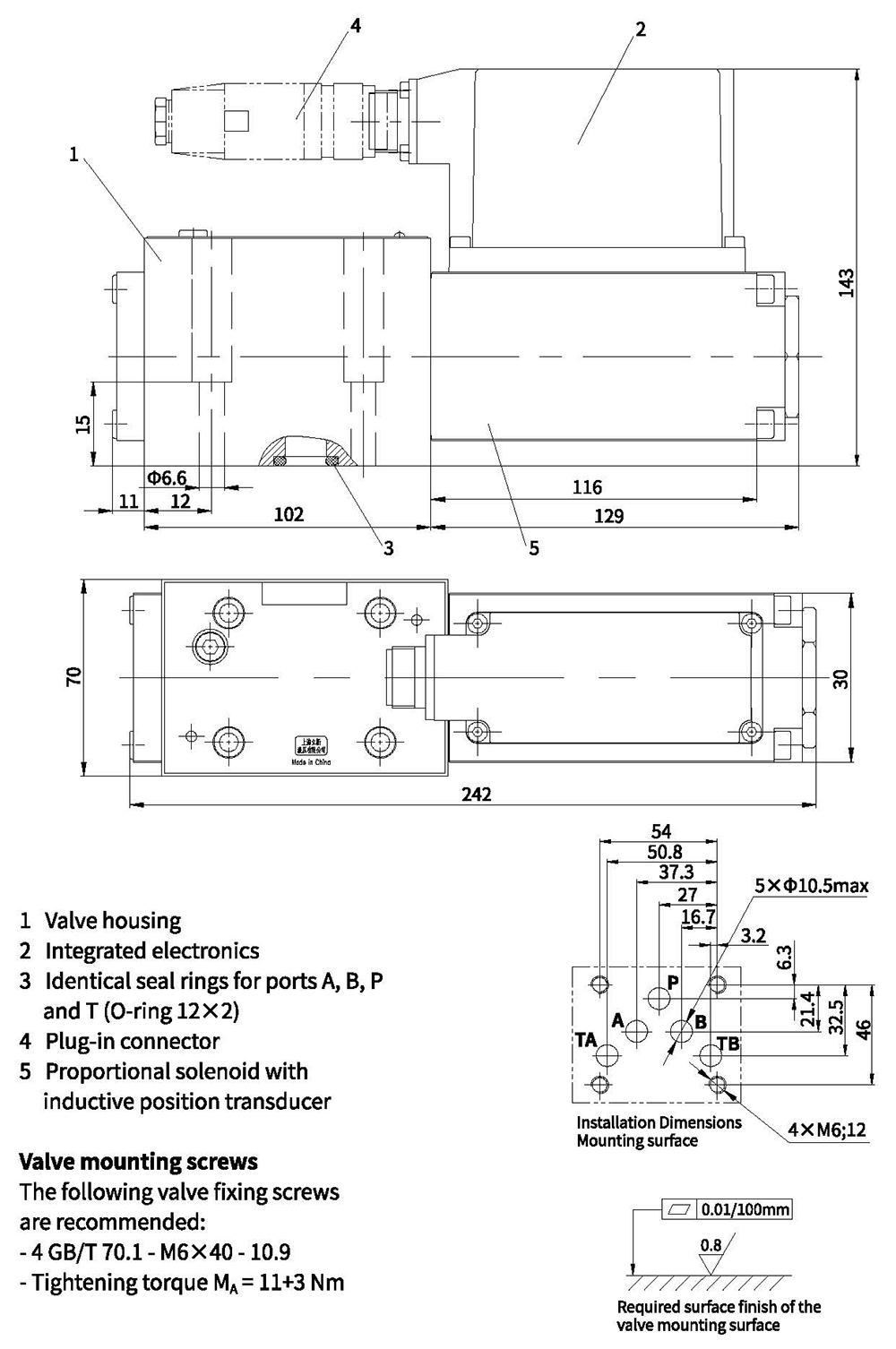
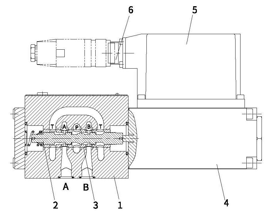
The valves basically consists of the housing (1), spool (2), sleeve(3), control solenoid with position transducer (4) and so on.
The specified command value is compared with the actual position value in the integrated electronics (OBE). In the event of a control deviation, the stroke solenoid is activated, which adjusts the control spool against the spring due to the change in the magnetic force.
Lifting/control cross-section is proportionally regulated to the command value. In case of a command value presetting of 0V, the electronics adjusts the control spool against the spring to central position. In deactivated condition, the spring is untensioned to a maximum and the valve is in fail-safe position.
With the electronics switched off, the valve moves immediately into the relevant safe basic position (fail-safe). The switch position P–B/A–T is passed through during this process, which can result in movements on the controlled component. This must be taken into account in system designs.
Type 4WRPEH10...-L2X/...
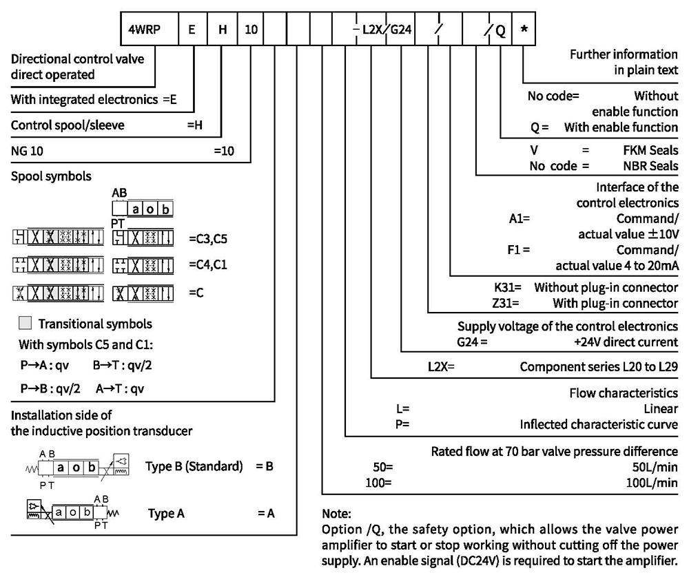
Ordering code
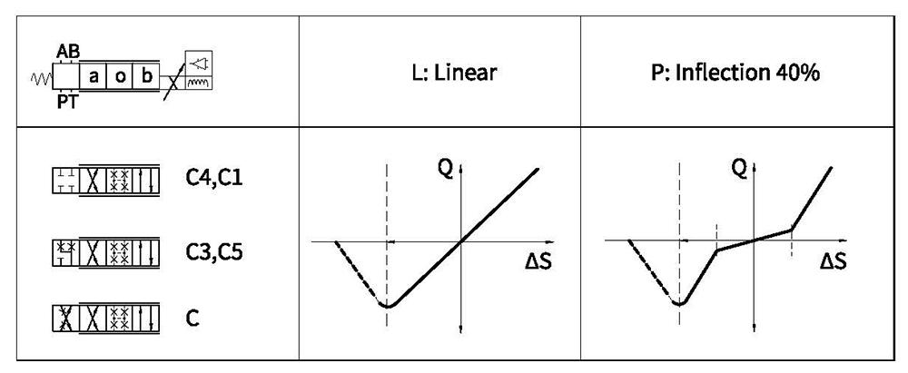
Symbols
Technical data
| General | ||||
| Design | Spool valve, directly operated, with steel sleeve | |||
| Actuation | Proportional solenoid with position control, OBE | |||
| Connection type | Plate port, porting pattern (ISO 4401-05-04-0-05) | |||
| Installation position | Any | |||
| Ambient temperature range | ℃ | -20...+50 | ||
| Weight | Kg | 7.1 | ||
| Maximum vibration resistance (test condition) | Max. 25 g, space vibration test in all directions (24h) | |||
| Hydraulic (measured with HLP 46, ,0ol=40℃±5℃) | ||||
| Hydraulic fluid | Hydraulic oil according to DIN 51524...535 | |||
| Viscosity range | Recommended | m㎡/s | 20...100 | |
| Max. admissible | m㎡/s | 10...800 | ||
| Hydraulic fluid temperature range | ℃ | -20 to+70 | ||
| Max.admissible degree of contamination of the hydraulic fluid, cleanliness class according to ISO 4406(c) | Class 18/16/13 | |||
| Rated flow(Δp=35 bar per edge) | L/min | 50 | 100 | |
| Maximum operating pressure | bar | Port P,A, B:315 | ||
| Maximum operating pressure | bar | Port T:250 | ||
| Leakage flow at 100 bar | Linear | cm3/min cm3/min | <1200 | <1500 |
| Nonlinear | <600 | <600 | ||
| Static/Dynamic | ||||
| Hysteresis | % | ≤0.2 | ||
| Actuating time for signal step 0...100% | ms | 25 | ||
| Temperature drift | Zero shif t<1% at ΔT=40℃ | |||
| Zero compensation | y±1% Ex factor | |||
Electric, control electronics integrated in the valve
| Relative duty cycle | % | 100ED |
| Protection class | IP 65 (with mating connector mounted and locked) | |
| Connection | Mating connector 6P+PE, DIN 43563 | |
| Supply voltage Terminal A Terminal B:0V | 24VDCnom | |
| min.21VDC/max.40VDC | ||
| Ripple max. 2 VDC | ||
| Fuse protection, external | AF | 2.5 |
| Input,version "A1" Terminal D (UE) Terminal E | Differential amplifier,F Ri=100kΩ | |
| 0...±10V | ||
| OV | ||
| Input,version "F1" Terminal D (Ip-E) Terminal E (ID-E) | Load,Rsh=200Ω | |
| 4...12...20mA | ||
| Current loop ID-Ereturn | ||
| Test signal, version "A1" Terminal F (UTest) Terminal C | LVDT | |
| 0...±10V | ||
| Reference 0 V | ||
| Test signal, version "F1" Terminal F(IFc) Terminal C(IF-c) | LVDT | |
| 4...20 mA output | ||
| Current loop l■c feedback | ||
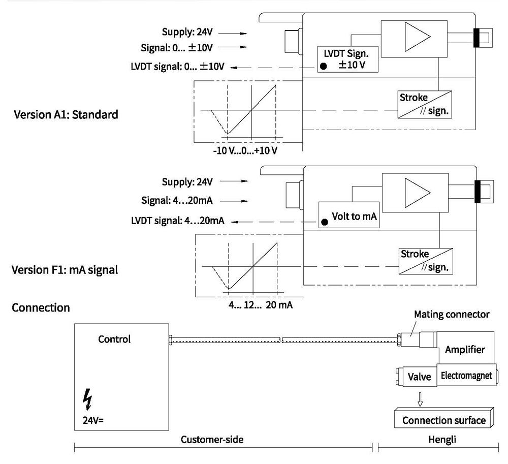
Electrical connection
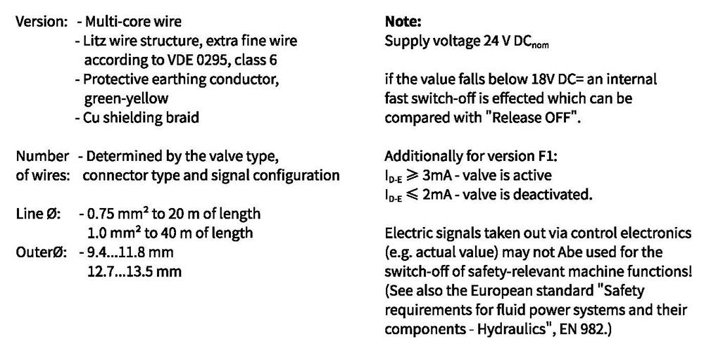
Technical data for the cable
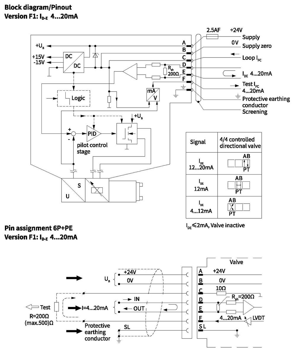
Integrated electronics
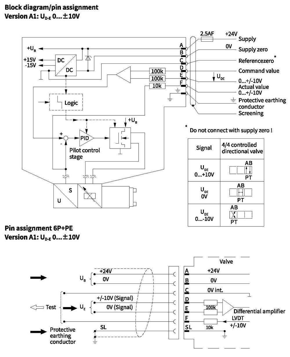
Integrated electronics
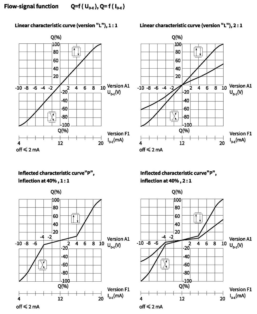
Characteristic curves(measured with HLP46, oil=40°C +5°C)
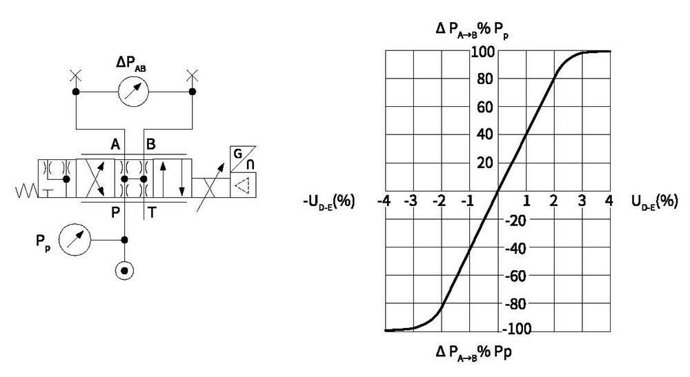
Characteristic curves: Pressure amplification(measured with HLP46, oil =40°C +5°C)
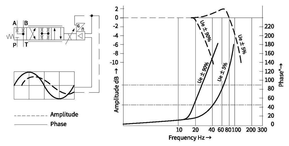
Characteristic curves: Bode diagram
Unit dimensions