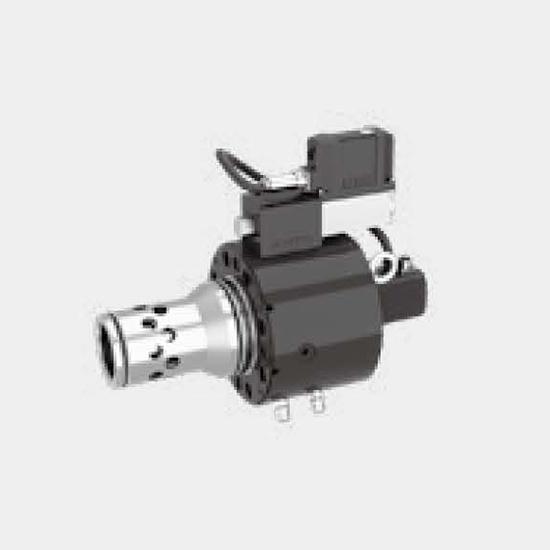
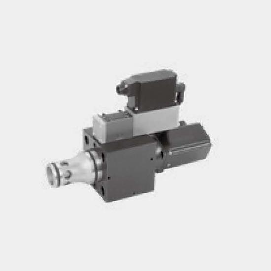
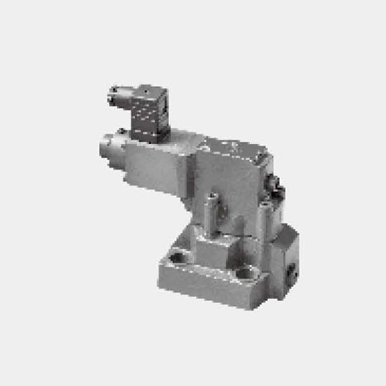
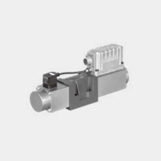
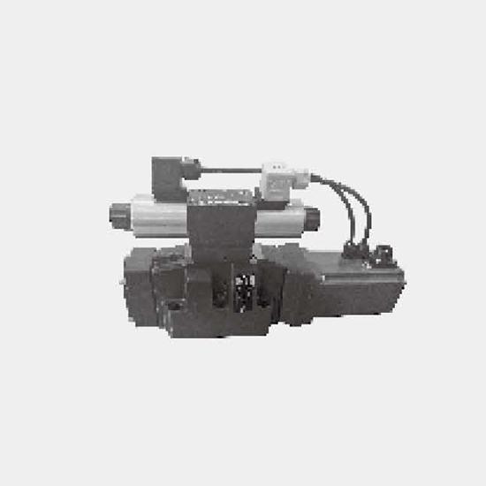
Function and configurationValves of type 2WRCVE...-L1X/P... is a pilot proportional servo cartridge valve with valve core position feedback and integrated amplifierSet-up:They consist of the following...
Product Detail
Function and configuration
Valves of type 2WRCVE...-L1X/P... is a pilot proportional servo cartridge valve with valve core position feedback and integrated amplifier
Set-up:
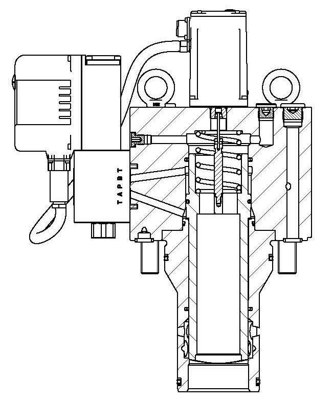
They consist of the following assemblies:
Pilot servo valve with spool valve sleeve structure driven by voice coil valve.
Main valve with reset spring and position feedback.
Main valve displacement sensor and main valve integrated amplifier.
Function:
The 2-way servo proportional valves TDP have a 2-stage design consisting of a pilot valve and a main stage with poppet and LVDT.
Due to the use of a voice coil motor as the pilot valve, the TDP achieves extremely fast response times: from 17ms (NG63) up to 28ms (NG100) with an accuracy of <0.1% of the nominal flow.
The pilot valve actively controls the poppet - independent of the pressure conditions in the main ports. It is basically required that the pilot pressure is at the level of the system pressure. At low system pressure the pilot pressure should be min. 140bar, when high valve dynamics are desired.
The pilot servo valve and main valve of the valve are each equipped with an integrated amplifier with a closed-loop control circuit, which control the main valve and the pilot valve.
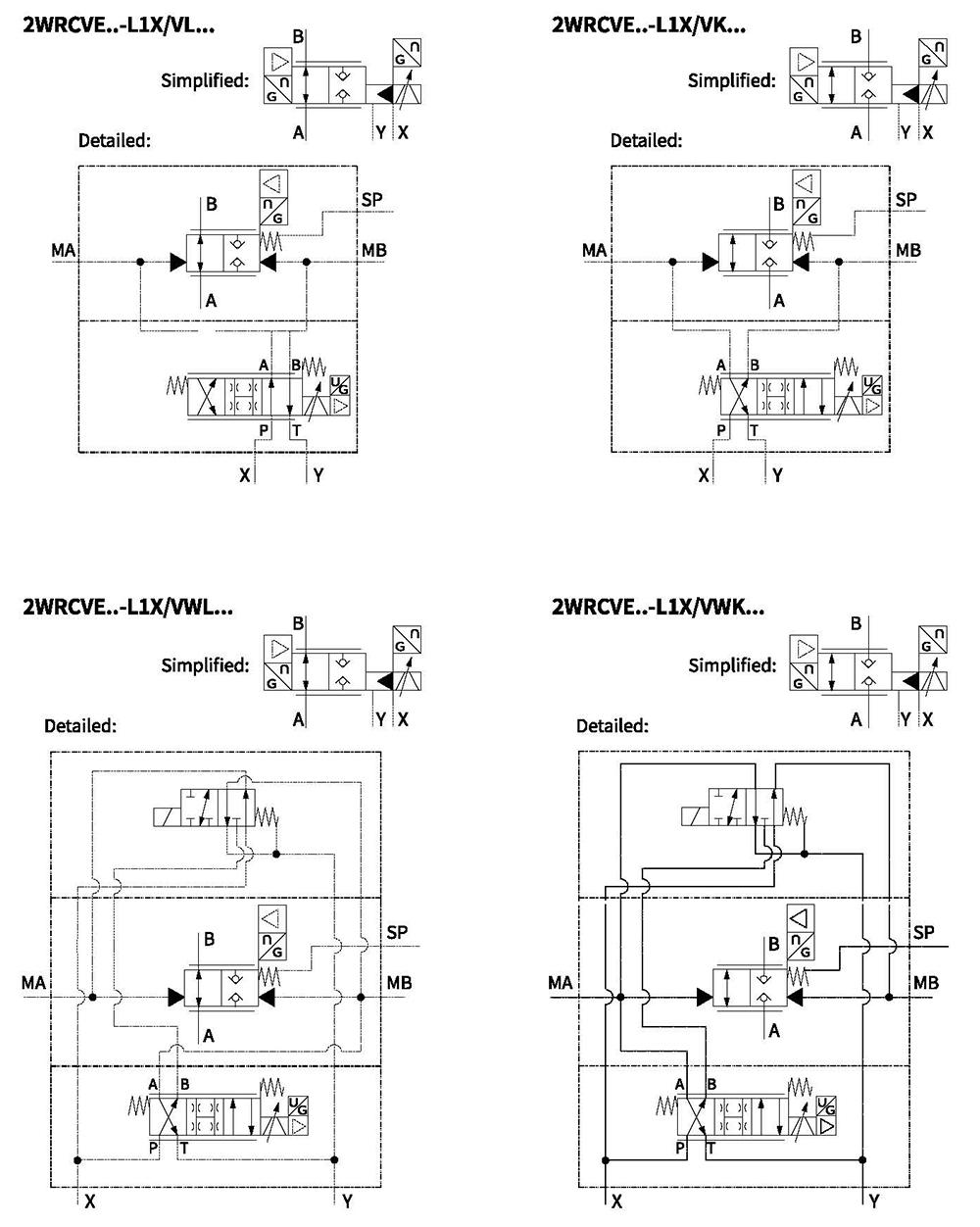
Symbols
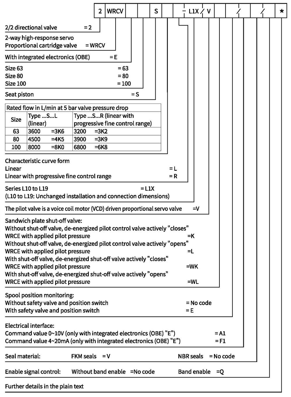
Ordering code
Technical data
| General | |||||
| Size | 63 | 80 | 100 | ||
| Weight | Without shut-off valve ...../...K or.../...L | kg | 47 | 74 | 110 |
| With shut-off valve ...../...WK or.../...WL | 60 | 87 | 123 | ||
| Installation position | Any, preferably horizontal | ||||
| Storage temperature range ℃ | -20 to+80 | ||||
| Ambient temperature range ℃ | -20 to+50 | ||||
| 0℃±5℃) Hydraulic (measured with HLP32, 4: 0oil= | |||||
| Max. operating pressures | -Pilot control valve port X | bar | 350 | ||
| -Ports A, B, SP | 350 | ||||
| -Port Y | 35 | ||||
| Rated flow at Δp=5bar | -Design...S...L (linear) | 3600 | 4500 | 8000 | |
| - Design...S...R (linear with progressive fine control range) | 3200 | 3900 | 6800 | ||
| Pilot valve pressure | bar | >140 | |||
| Max. pilot flow at 140bar pilot pressure | L/min | 70 | 80 | 100 | |
| Leakage of pilot valve at P=100bar | mL/min | ≤400 | |||
| Hydraulic fluid | Mineral oil (HL, HLP) to DIN 51524 | ||||
| Hydraulic fluid temperature range | ℃ | -20to +80; preferably +40 to +50 | |||
| Viscosity range | m㎡/s | 20 to 380; preferably 30 to 45 | |||
| Max. admissible degree of contamination of the hydraulic fluid, cleanliness class according to ISO 4406(c) | Class 20/18/15 | ||||
| Hysteresis | % | ≤0.1 | |||
| Response sensitivity | % | ≤0.05 | |||
| Response time 0~100% step signal | ms | 17 | 23 | 28 | |
| Electric | |||
| Duty ratio | % | 100 | |
| Supply voltage/ripple | VDC | Direct voltage 22...30, electric shut-off at<19, ripple <5% effective, surge free | |
| Current consumption max. | A | 3.5 | |
| Pre-fusing | A | 4.0, medium lag | |
| Input signal: A1 | Voltage | V | 0···+10, ripple<0.01%, effective, surge free |
| Impedance | kΩ | 100 | |
| Input signal: F1 | Current | mA | +4···20, ripple < 0.01% effective, surge free, <3.6mA=disable,>3.8mA=enable |
| Impedance | Ω | <250 | |
| Diagnostic signal | Voltage | V | 0···+10, rated max.5mA |
| Enable signal | V | 5...30,Ri=>8kOhm | |
| Electrical connection | 6+PE, plug-in connector in accordance with DIN EN 175201-804 standard | ||
| Protection class of the valve according to EN60529 | lp65 | ||
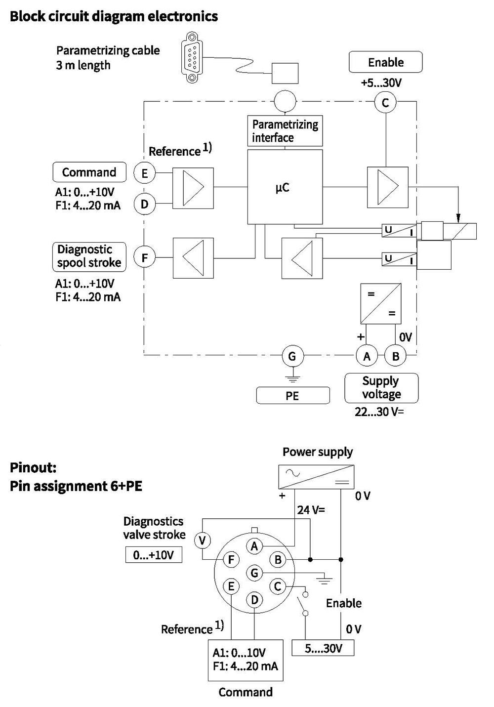
Electrical connections, plug-in connectors
Installation recommendations
An insufficient pilot oil supply (e.g. due to long distances and/or small diameters) can negatively influence the dynamics of the valve.
To avoid this, an accumulator can be connected to port XX at the valve body. A short-term undersupply with pilot oil can be compensated via this accumulator.
Sizing data: see operation manual.
Please also consider the product range of Hengli batteries and Hengli Accumulator Sizing Software.
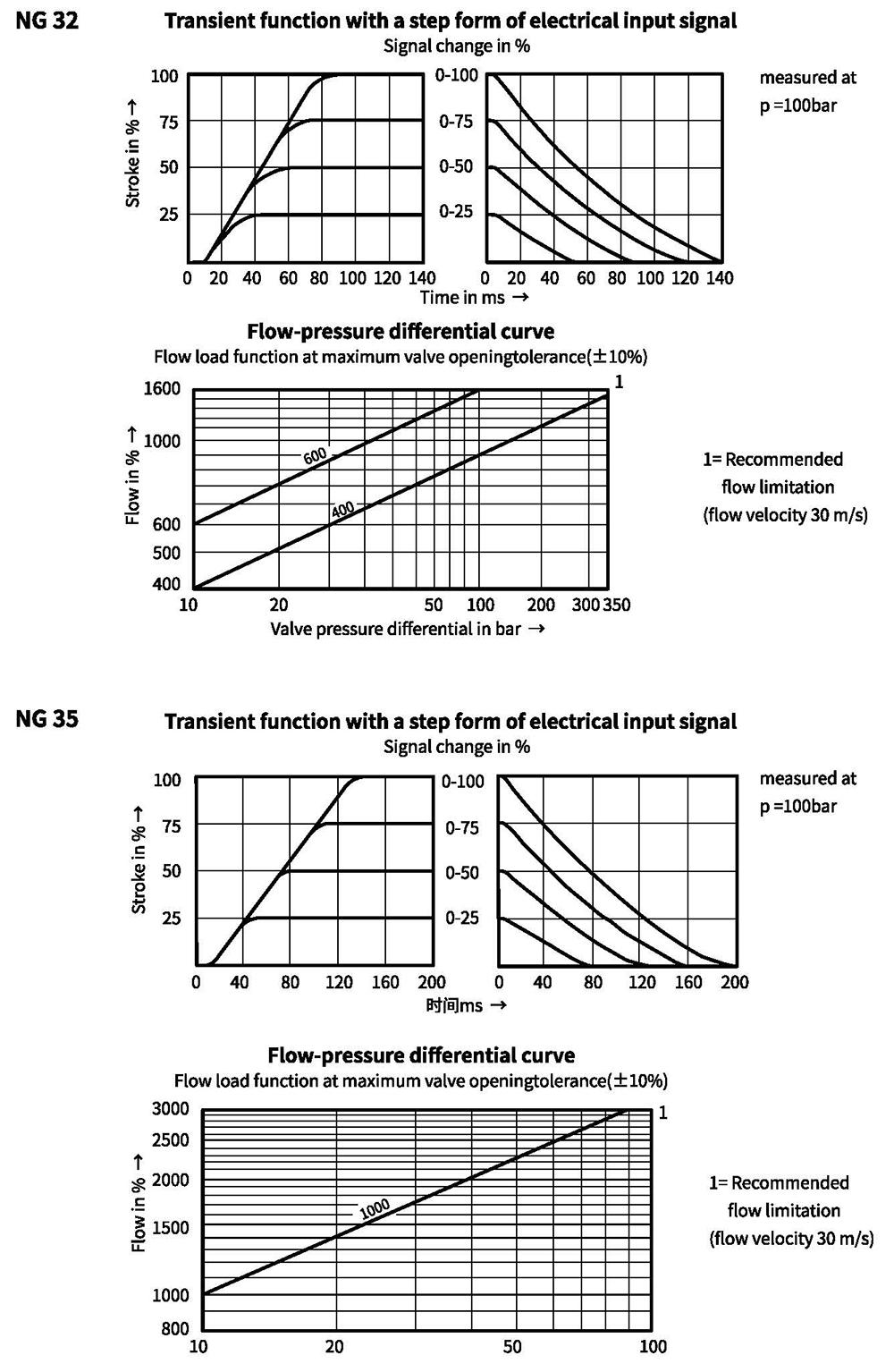
Characteristic curves(measured with HLP46, oil =50°C, AP=5bar)
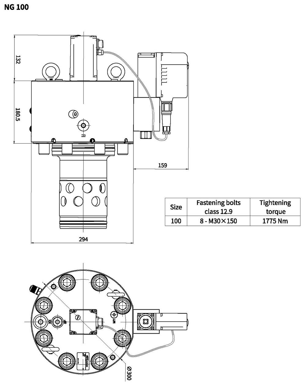
Unit dimensions
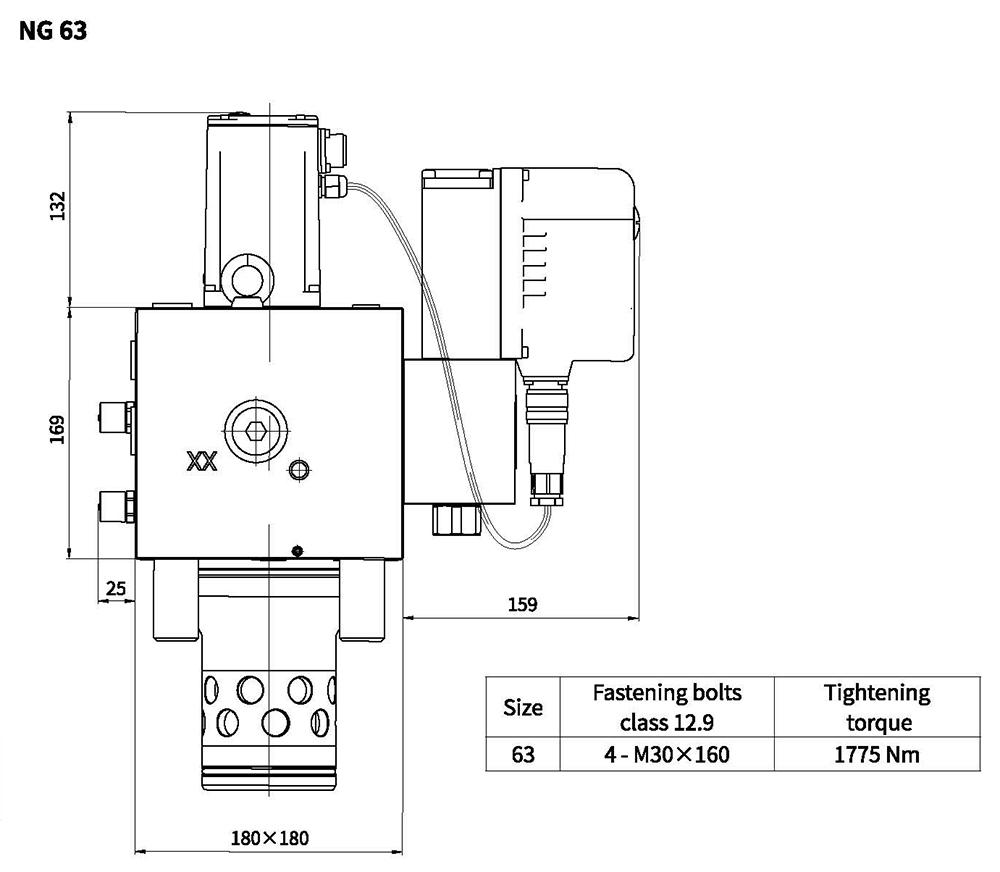
Unit dimensions
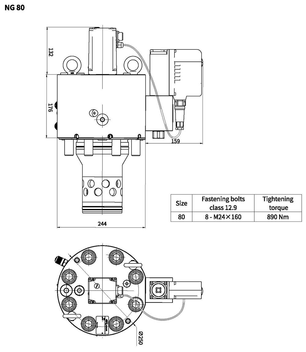
Unit dimensions
Installation dimensions according to DIN ISO 7368
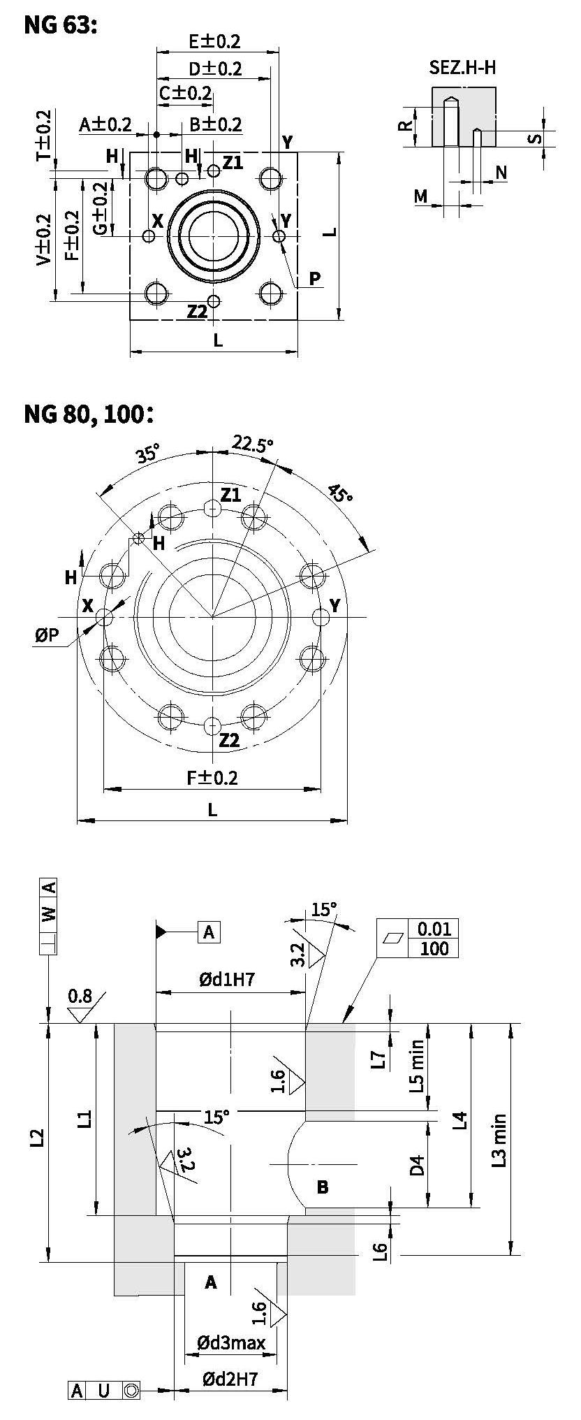
| Size | 63 | 80 | 100 |
| A | 12.5 | - | - |
| B | 24.5 | - | - |
| C | 62.5 | - | - |
| D | 125 | - | - |
| E | 137.5 | - | - |
| F | 125 | 200 | 245 |
| G | 62.5 | - | - |
| Lmin | 180 | 250 | 300 |
| M | M30 | M24 | M30 |
| ØN | 8 | 10 | 10 |
| ØP max | 12 | 16 | 20 |
| R | 66 | 50 | 66 |
| Smax | 8 | 8 | 10 |
| T | 12.5 | - | - |
| V | 137.5 | - | - |
| Ød1 | 120 | 145 | 180 |
| Ød2 | 90 | 110 | 135 |
| Ød3 max | 63 | 80 | 100 |
| Ød4 max | 87 | 100 | 120 |
| L1 | 130 +0.1 0 | 175 +0.2 0 | 210 +0.2 0 |
| L2 | 155 +0.1 0 | 205 +0.2 0 | 245 +0.2 0 |
| L3 | 150 | 200 | 239 |
| L4 | 127 | 170.5 | 205.5 |
| L5 | 40 | 40 | 50 |
| L6 | 4 | 5 | 5 |
| L7 | 4 | 5 | 5 |
| U | 0.05 | 0.05 | 0.05 |
| W | 0.2 | 0.2 | 0.2 |