Product Detail
Function and configuration
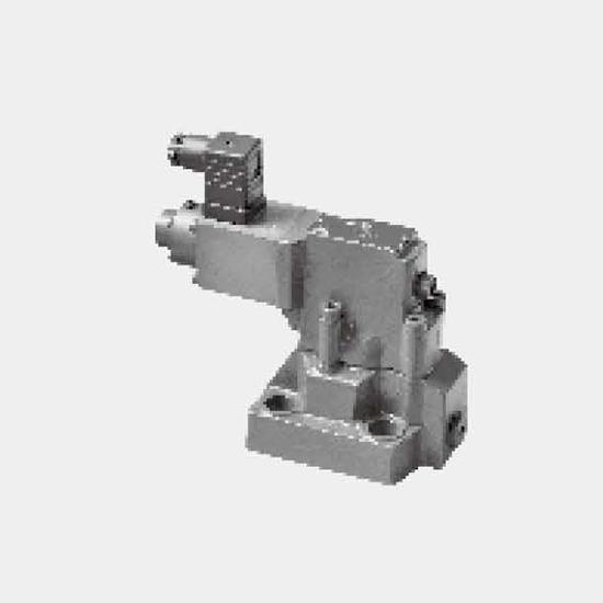
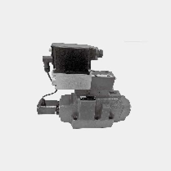
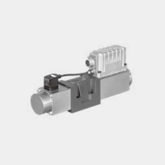
DBE valves are pilot operated pressure relief valves. They are used to continuously set the pressure in hydraulic systems by electrical signal.
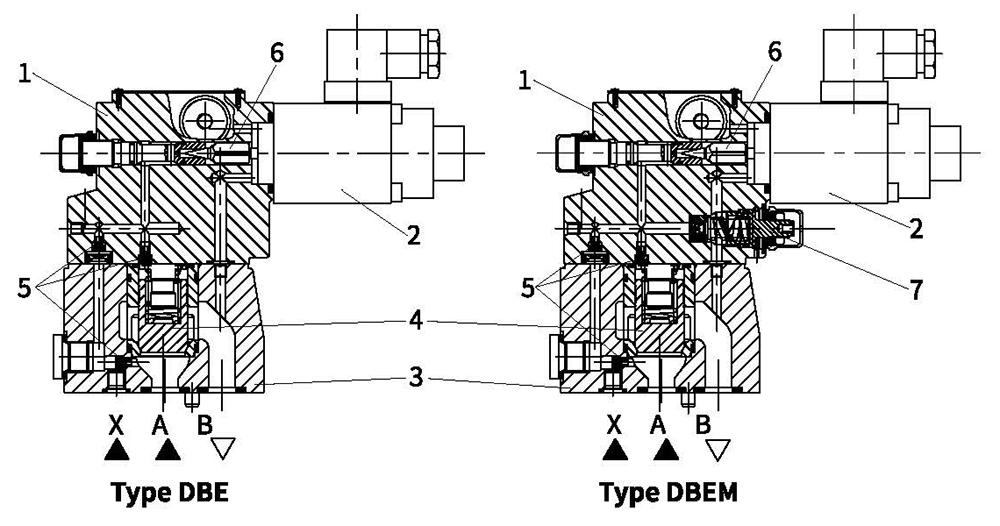
Basically these valves consist of a pilot valve (1) with proportional solenoid (2) and the main valve (3) with main spool insert (4).
Type DBE...
The pressure limit is in relation to the electrical current value and set by the proportional solenoid (2).
The system pressure is applied to the main spool (4). At the same time the pressure is applied to the spring loaded side of the main spool (4) and the pilot poppet (6) via orifice (5) at the pilot valve (1). If the hydraulic force exceeds the solenoid force, the pilot poppet (6) opens. Pilot fluid can flow back to tank and pressure drop caused by the orifices effects the main spool (4). Then main spool (4) opens the channel from pump to tank.
Type DBEM…
Optionally the valve can be supplied with an additional spring loaded pilot control valve (7) for maximum pressure safety (redundant pressure safety).
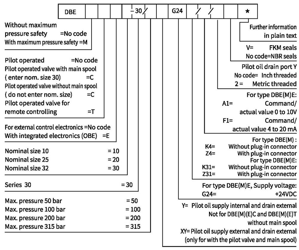
Ordering code
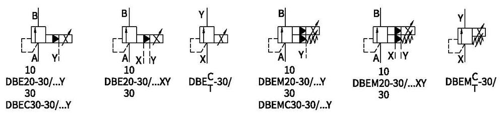
Symbols
Technical data
| Fluid | Mineral oil suitable for NBR and FKM seal | |||
| Phosphate ester for FKM seal | ||||
| Fluid temperature range | ℃ | -30 to +80 (NBR seal) | ||
| -20 to +80 (FKM seal) | ||||
| Viscosity range | m㎡/s | 2.8 to 380 | ||
| Degreeof contamination | Maximum permissible degree of fluid contamination: Class 9. NAS 1638 or 20/18/15, ISO4406 | |||
| Max.operating pressure Port A, B,X | bar | 315 | ||
| Max.setting pressure | bar | 50;100;200;315 | ||
| Min.setting pressure | In relation to Flow (Q), see characteristic curves | |||
| Pressure at zero command value | = min.setting pressure | |||
| Return oil pressure port Y | bar | Separate and at zero pressure to tank | ||
| Max. pressure safety (infinitely adjustable) | setting pressure | Pressure range under Max. safety pressure | ||
| 50 bar | 10-60+20 bar | |||
| 100 bar | 10-120+20 bar | |||
| 200 bar | 10-220+20bar | |||
| 315 bar | 10-340+20 bar | |||
| Max.pressure safety setting condition | When rated pressure is 50 bar, between 60 bar and 80 bar | |||
| When rated pressure is 100 bar, between120 bar and 140 bar | ||||
| When rated pressure is 200 bar, between 220 bar and 240 bar | ||||
| When rated pressure is 315 bar, between 340 bar and 360 bar | ||||
| Nominal size | 10 | 25 | 32 | |
| Max.flow-rate | L/min | 200 | 400 | 600 |
| Pilot oil (for pilot valve) | L/min | 0.7 to 2 | ||
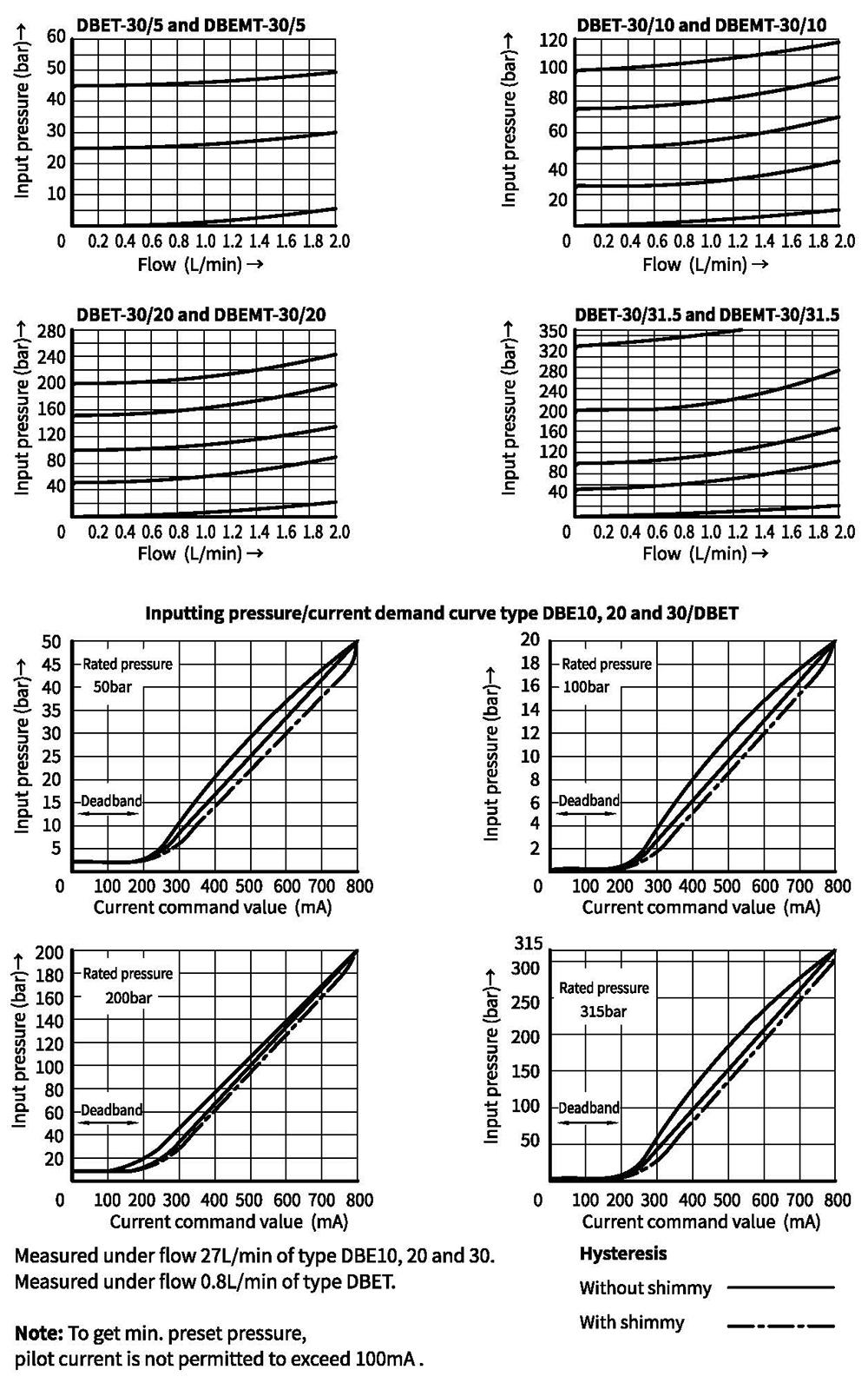
| Linearity | ±3.5% | |||
| Repeatability | <±2% | |||
| Hysteresis | with shimmy | without shimmy | ||
| ±1.5% P max (200Hz,amplitude 200mAssl) | ±4.5% P max | |||
| Shifting time | 30~150ms (undependent with the system) | |||
| Electrical | |
| Power source | DC |
| Min. solenoid current mA | 100 |
| Max.solenoid current mA | 800 |
| Coil resistance | 19.5Ω at 20℃, Max.warm value:28.8Ω |
| Working status | Continuous |
| Max.working enviromental temperature | +50℃ |
| Electrical connection | Plug-in connector to DIN EN 175301-803/ISO 4400 |
| Insulation to DIN 40 050 | IP 65 |
| Ampilfier | VT2000 |
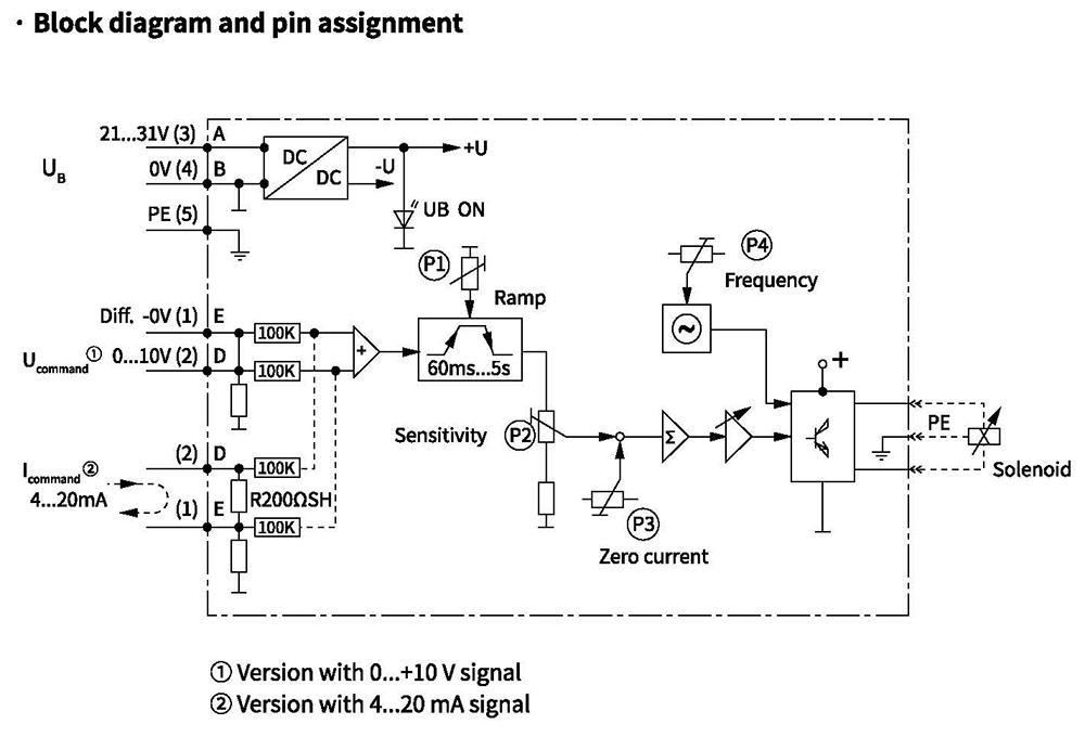
Proportional amplifier (Can be ordered separately)
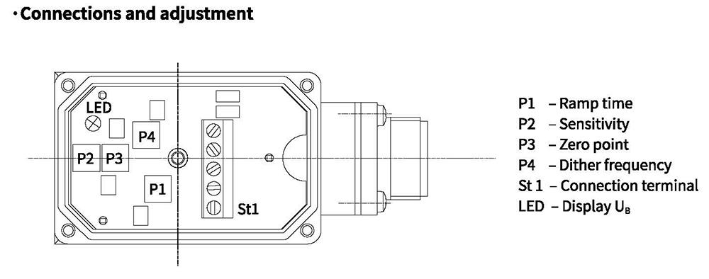
Electrical connections, plug-in connectors
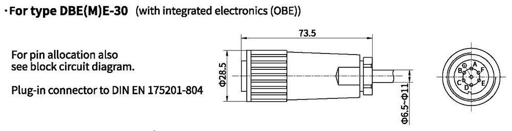
·Component plug allocation
| Contact | Interface A1 signal | Interface F1 signal | |
| Supply voltage | A | 24 VDC(U(t)=21V to 31V) | |
| B | GND | ||
| C | n.c.1) | ||
| Differential amplifier input | D | ±10V,Re>50KΩ | 4 to 20mA, Re>100Ω |
| E | reference potentional command value | ||
| F | n.c. | ||
1)Contacts C and F must not be connected!
Electrical connections, plug-in connectors
Characteristic curves(Measured at oil=40°C I5°C,using HLP46)
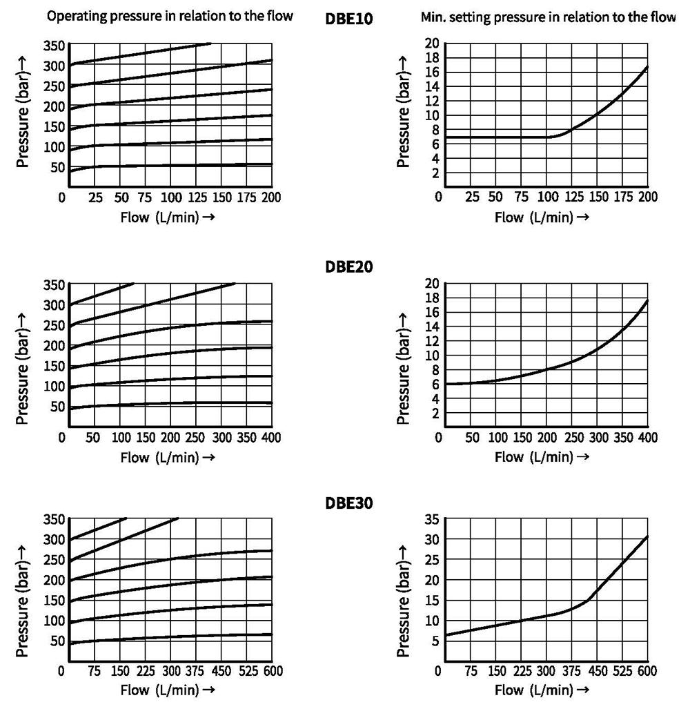
Characteristic curves(Measured at oil =40°C +5°C, using HLP46)
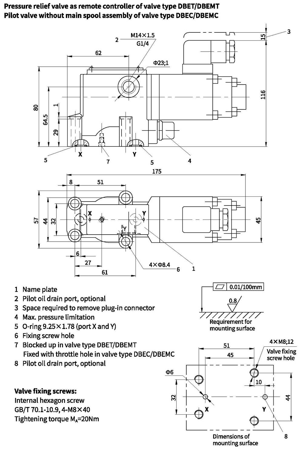
Unit dimensions
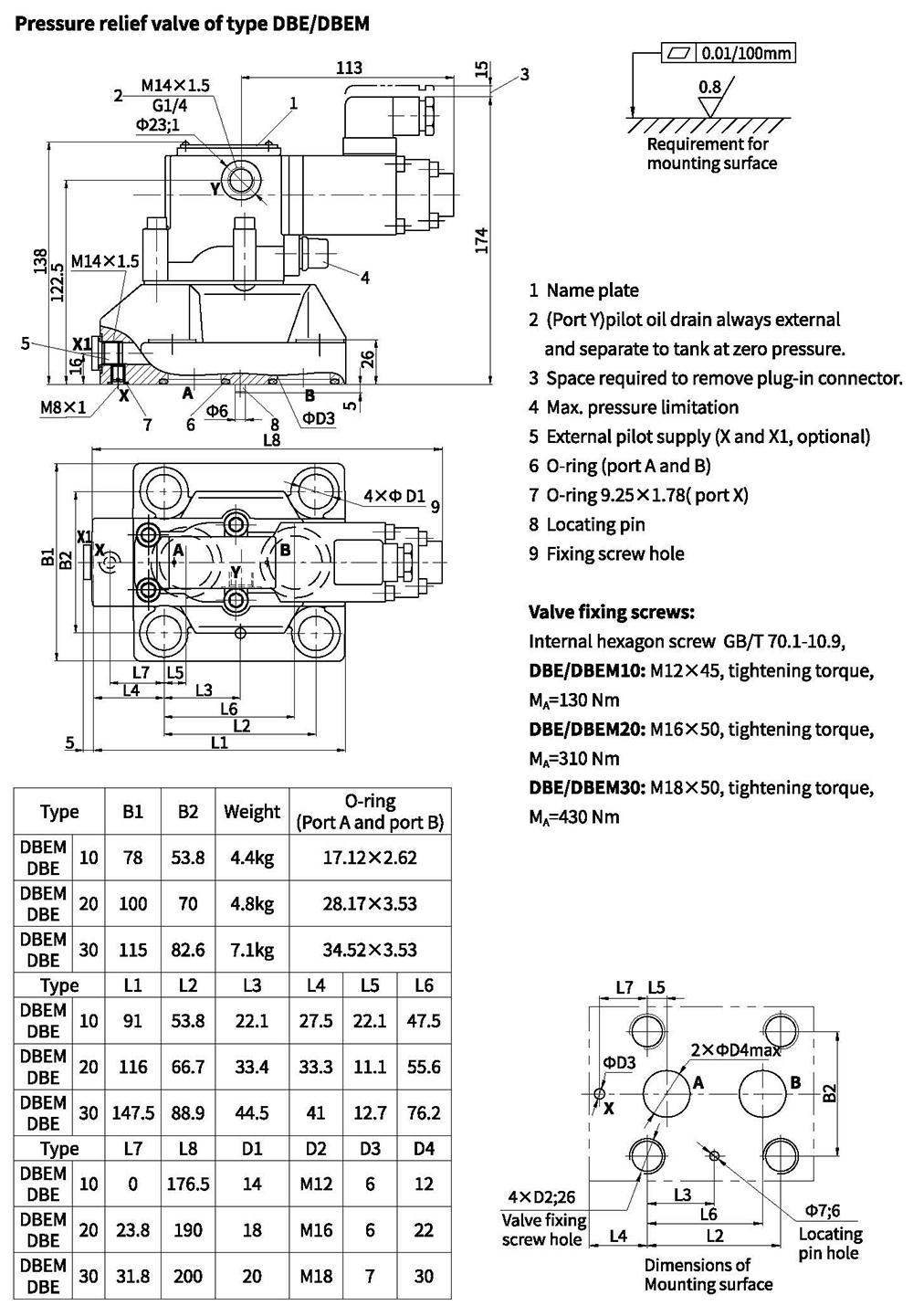
Unit dimensions
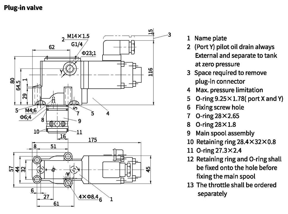
| Size | D1 | D2 | D3 | Main spool assembly code | Valve fixing screw | Tighting touque | Weight | |
| 10 | 10 | 40 | 10 | 307341 (NBR) | 307342 (FKM) | 4-M8x40 internal hexagon GB/T70.1-10.9 | 20Nm | 2.9kg |
| 20 | 25 | 45 | 25 | |||||
| 30 | 32 | 45 | 32 | |||||
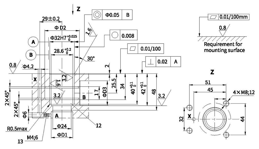
Unit dimensions