Function and configurationProportional directional valve:type 4WRKE...L3X...The type 4WRKE valves are 2-stage proportional directional control valves. They control the size and direction of a flow.The...
Product Detail
Function and configuration
Proportional directional valve:
type 4WRKE...L3X...
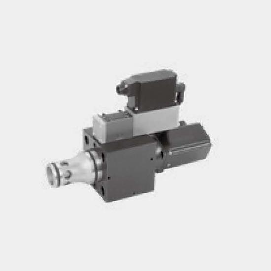
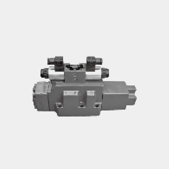
The type 4WRKE valves are 2-stage proportional directional control valves. They control the size and direction of a flow.
The main stage is closed loop position controlled so that the spool position is also independent of flow forces at larger flows.
Structure
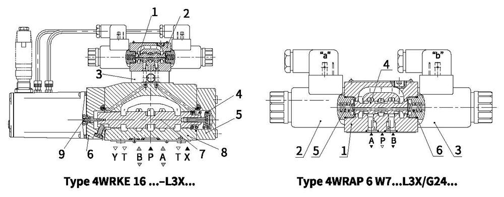
The valves basically consists of the pilot control valve (1), housing (8), main spool (7), covers (5 and 6), centering spring (4), inductive position transducer (9) and the pressure reducing valve (3).
Function
— If no input signal is being applied then the main spool (7) is held in the center position by the centering spring (4). The two control chambers in the covers (5 and 6) are connected via the valve spool (2) to tank.
— The main spool (7) is connected to suitable control electronics via the inductive position transducer (9). The positional change of the main spool (7) as well as the alteration of the command value at the summation point of the amplifier produces a differential voltage.
With the command value/actual value comparison a possible control deviation is recognised via the electronics and an electrical current is applied to the proportional solenoid of the pilot valve (1).
The current induces, within the solenoid, a force which is passed on to the solenoid pin which in turn actuates the control spool. The flow which is provided via the control cross sections causes the main spool to move.
Pilot control valve :
type 4WRAP 6 W7...-L3X/G24...(1st stage)
The pilot control valve is a direct operated proportional valve. The control edge geometries were designed and optimised for the use as a pilot control valve for the proportional directional valves type 4WRKE.
The proportional solenoids are pressure tight, oil-immersed DC solenoids with removable coil. They convert an electrical current proportionally into a mechanical force. An increase in the current strength causes an appropriately higher solenoid force.
Structure
The pilot control valve basically consists of the housing (1), proportional solenoids (2 and 3), valve spool (4) and springs (5 and 6).
In the de-energised condition both actuator ports are connected to tank. If one of the two solenoids (2 or 3) is energised, then the solenoid force moves the valve spool (4) against the spring (6 or 5). Once the overlap area is overcome, the connection to tank of one of the two actuator ports is blocked and the connection to the pressure chamber is established. There is flow from P to the control chamber of the main stage.
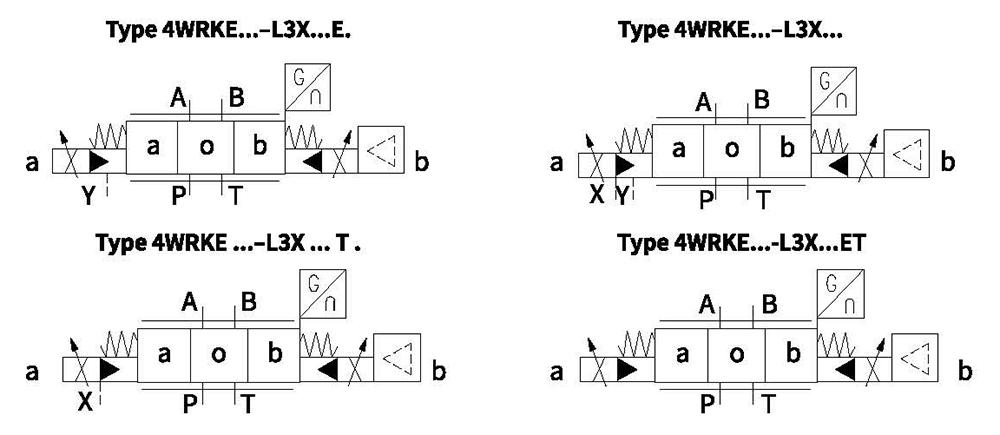
Symbols (simplified)
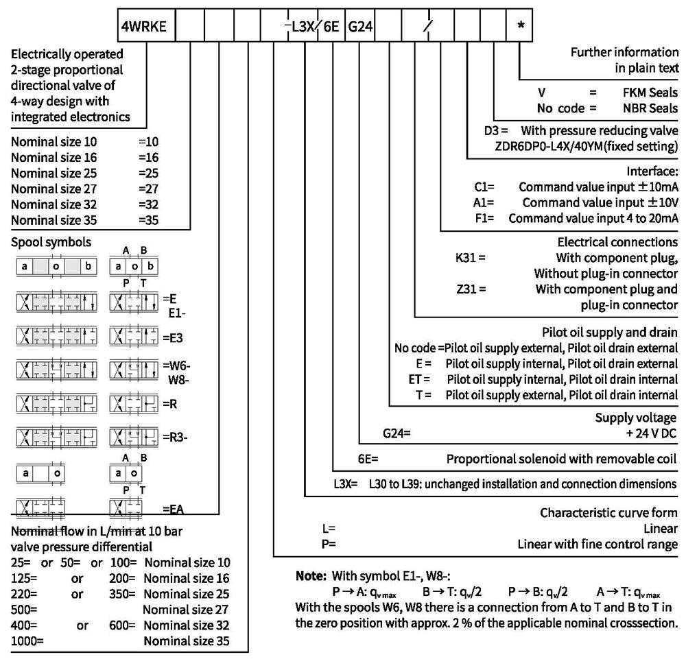
Ordering code
Technical data
| General | |||||||
| Nominal size | 10 | 16 | 25 | 27 | 32 | 35 | |
| Installation and commissioning guidelines | Optional, preferably horizontal | ||||||
| Storage temperature range | ℃ | -20 to+80 | |||||
| Ambient temperature range | ℃ | -20 to+50 | |||||
| Weight | kg | 8.7 | 11.2 | 16.8 | 20 | 37.2 | 72 |
| Hydraulic(measured at p=100bar,with HLP46 at θoil=40℃±5℃) | ||||||||||
| Operating -Pilot control valve pressure -Main valve | Pilot oil supply | bar | 25 to 315 | |||||||
| Ports P,A,B | bar | Up to 315 | Up to 350 | Up to 350 | Up to 210 | Up to 350 | Up to 350 | |||
| Return pressure | Port T (Pilot oil drain) | Internal | bar | Static<10 | ||||||
| External | bar | Up to 315 | Up to 250 | Up t o 250 | Up to 210 | Up to 250 | Up to 250 | |||
| Port Y | bar | Static<10 | ||||||||
| Nominal flow qvnom ±10% at Δp=10bar (Δp =valve pressure differential) | L/min | 25 50 | - 125 | - 220 | - - | - 440 | - - | |||
| 100 | 180 | 350 | 500 | 600 | 1000 | |||||
| Flow of main valve (max. permissible) | L/min | 170 | 460 | 870 | 1000 | 1600 | 3000 | |||
| Pilot oil flow at port X or Y with a step form of input signal from 0 to 100 % (315 bar) | L/min | 4.1 | 8.5 | 11.7 | 11.7 | 13 | 13 | |||
| Pressure fluid | Mineral oil(HL,HLP)to DIN 51 524 Phosphate ester (HFD-R) | |||||||||
| Pressure fluid temperature range | ℃ | 10 to 80, preferably 40 to 50 | ||||||||
| Viscosity range | m㎡/s | 20 to 380,preferably 30 to 45 | ||||||||
| Degree of contamination | Maximum permissible degree of contamination of the pressure fluid is to NAS 1638. | A filter with a minimum retention rate of βx=75 is recommended | ||||||||
| Pilot control valve | Class 7 | |||||||||
| Main valve | Class 9 | x=7 | ||||||||
| Hysteresis | % | ≤1 | ||||||||
| Response sensitivity | % | ≤0.5 | ||||||||
| Electrical | ||
| Voltage type | DC | |
| Electrical connection | Plug-in connector to DIN EN175 201-804 | |
| Power, max. | W | 72 (average=24W) |
| Control electronics | Integrated into the valve | |
Electrical connections, plug-in connector
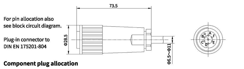
| Contact | Signal | |
| Supply voltage | A | 24 VDC (18 to 35 VDC); Imax = 1, 5 A; impulse load ≤ 3 A |
| B | OV | |
| Ref. (actual value) | C | Ref.potential for actual value (contact F) |
| Differential amplifierinput (command value) | D | ±10V or 4-20mA |
| E | OV ref. potentional | |
| Measurement output (act. value) | F | ±10V or 4-20 mA |
| PE | Connected with cooling body and valve housing |
Command value:
Reference potential at E and a positive command value at D results in a flow from P to A and B to T.
Reference potential at E and a negative command value at D results in a flow from P to B and A to T.
Connection cable:
Recommendation: – Up to 25m cable length type LiYCY 7×0.75 mm²
– Up to 50m cable length type LiYCY 7×1.0 mm²
External diameter: – 6.5 to 11mm (plastic plug-in connection)
– 8 to 12mm (metal plug-in connector)
Connect screen to ⊥ only on supply side.
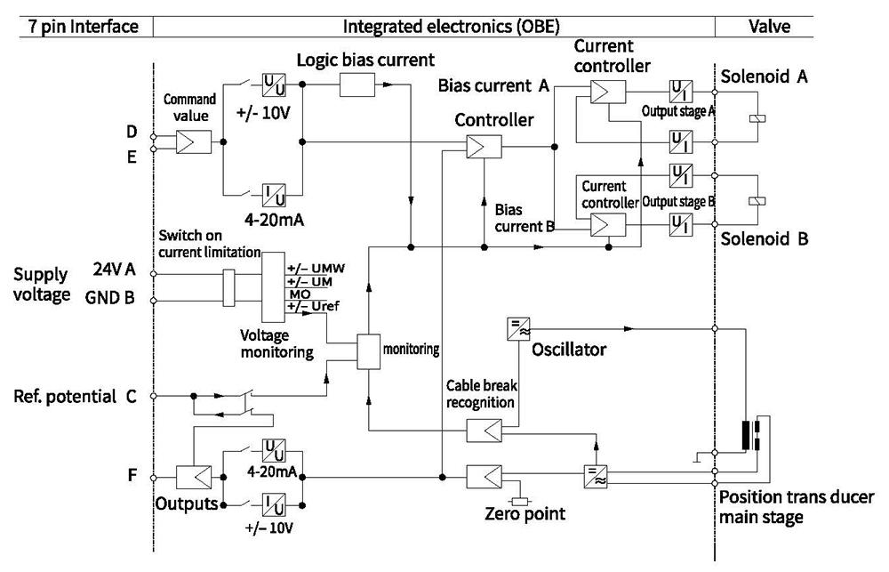
Blockcircuit diagram / connection allocation of the integrated control electronics for type 4WRKE
Characteristic curves(measured with HLP46, oil=40°C +5°C)
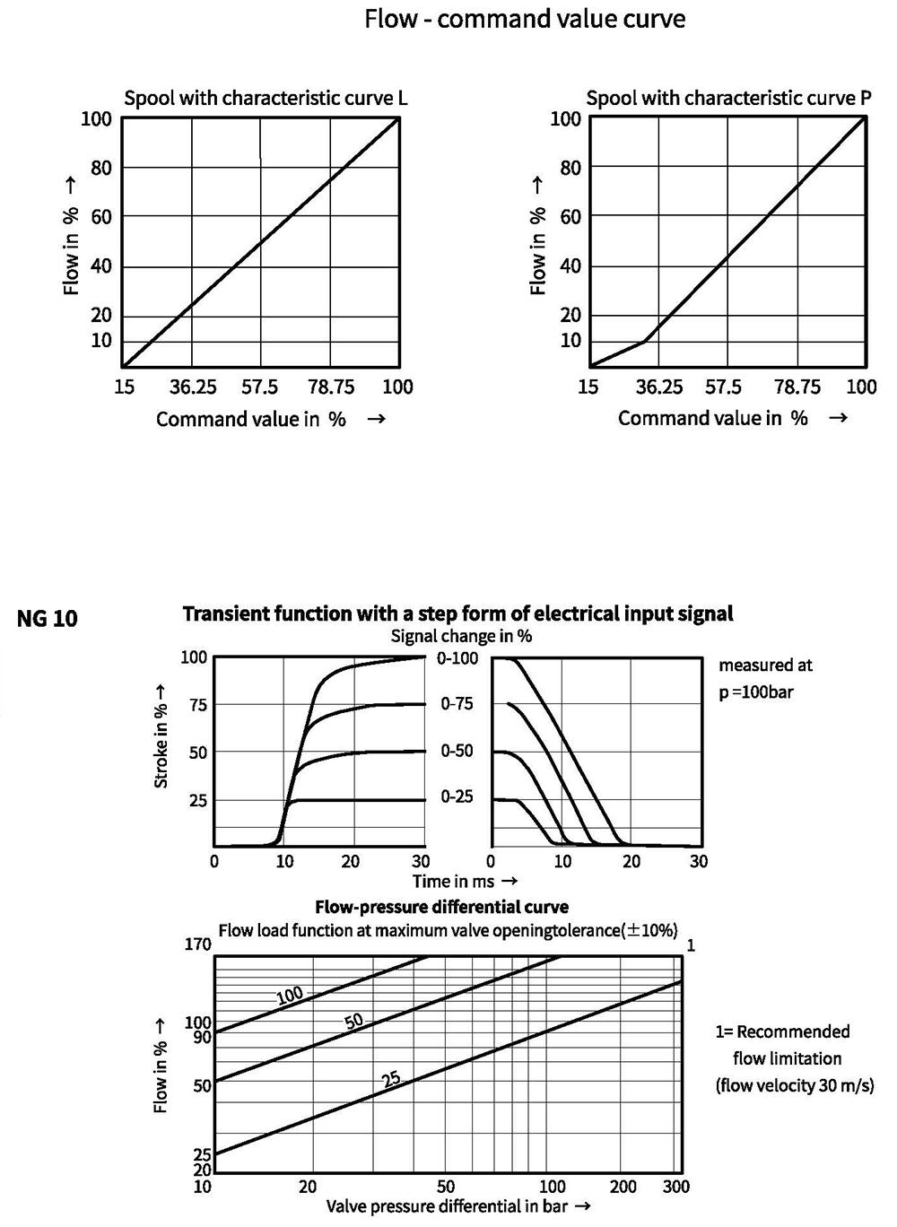
Characteristic curves(measured with HLP46, oil =40°C +5°C)
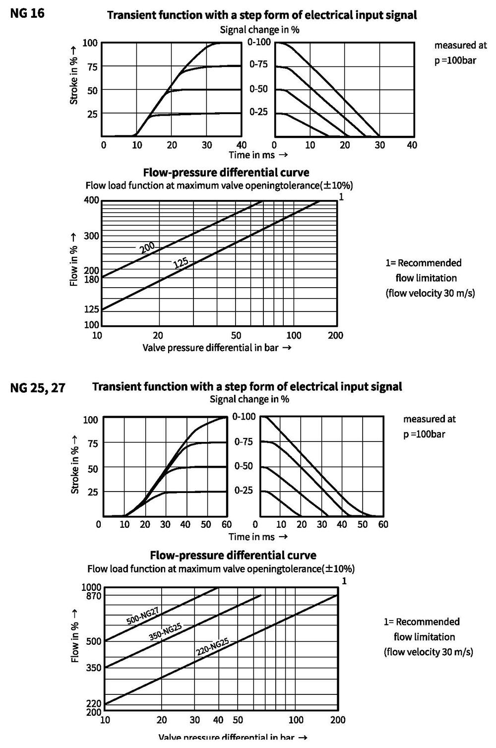
Characteristic curves(measured with HLP46, oil=40°C +5°C)
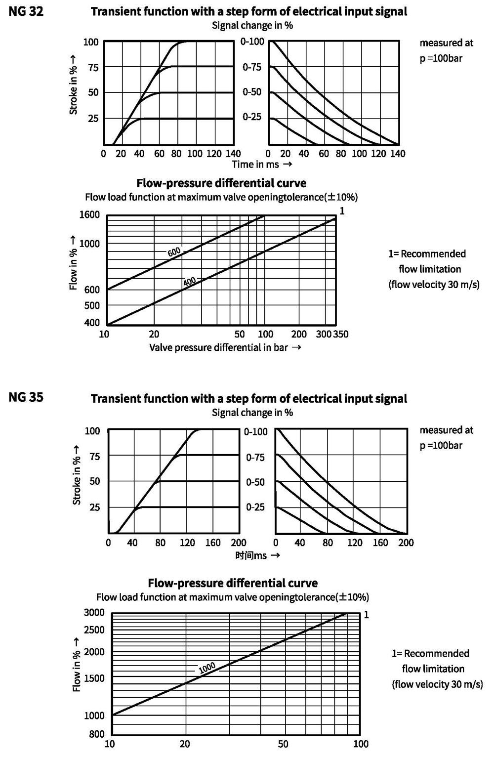
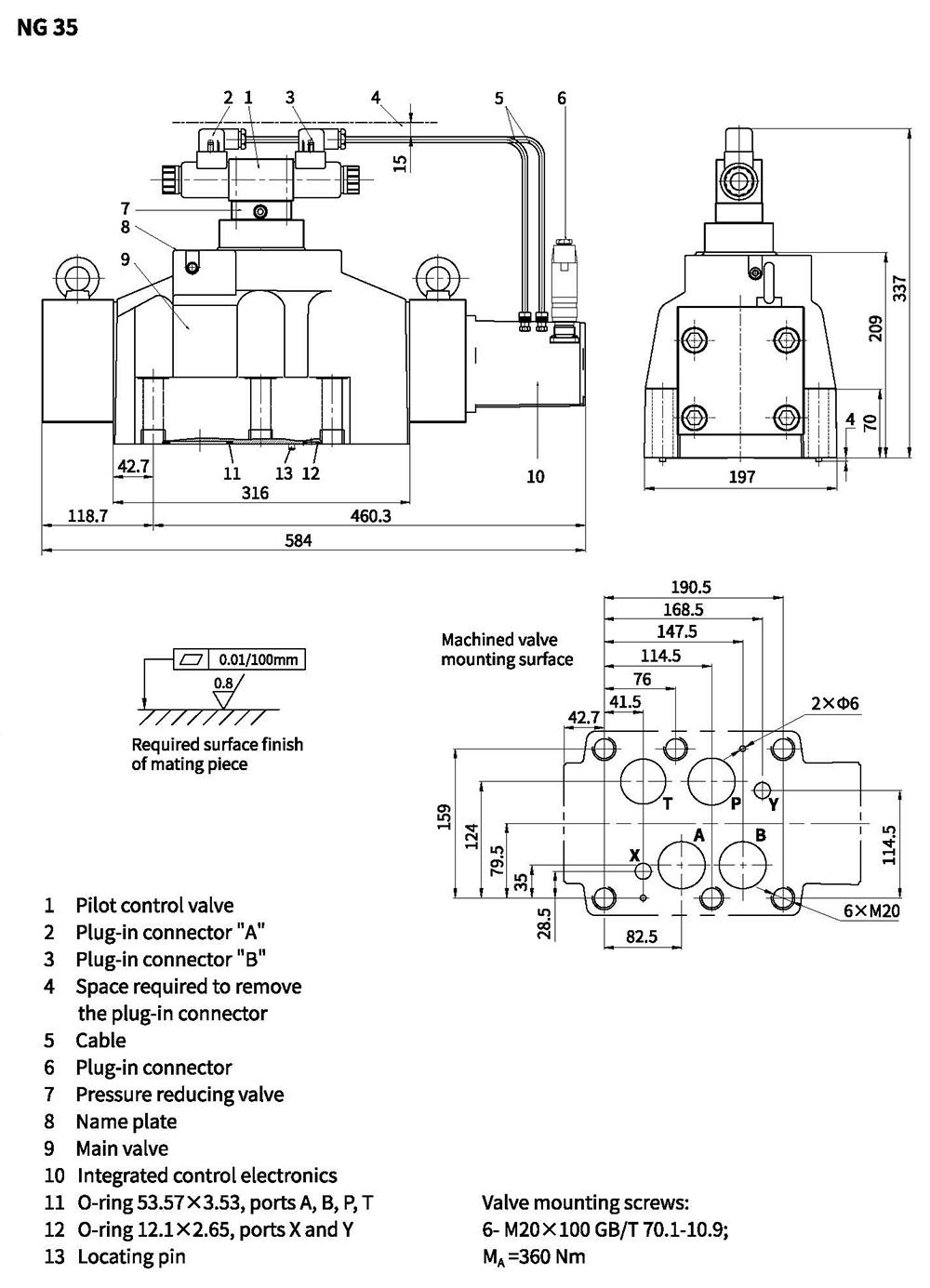
Unit dimensions
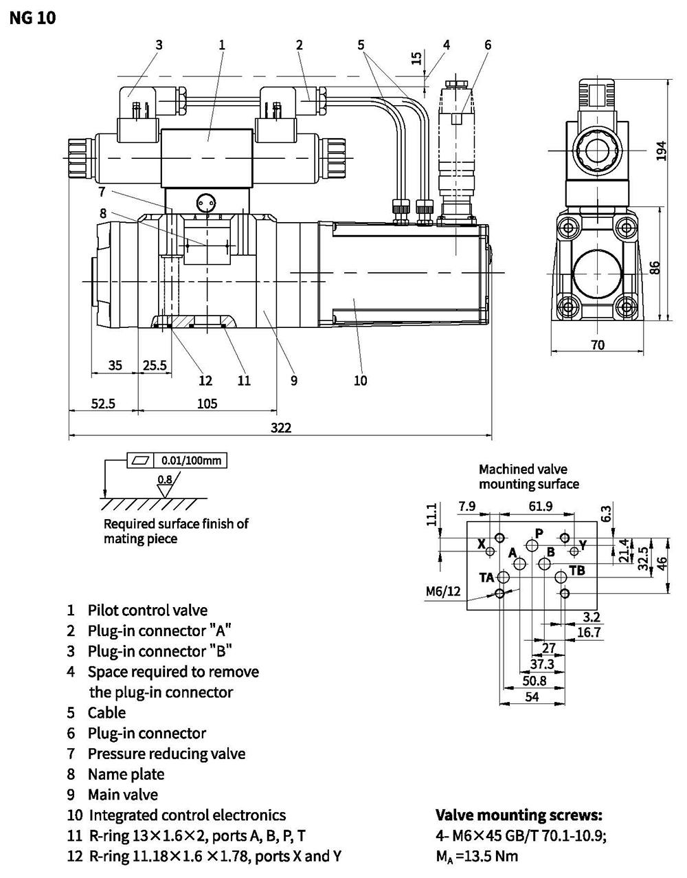
Unit dimensions
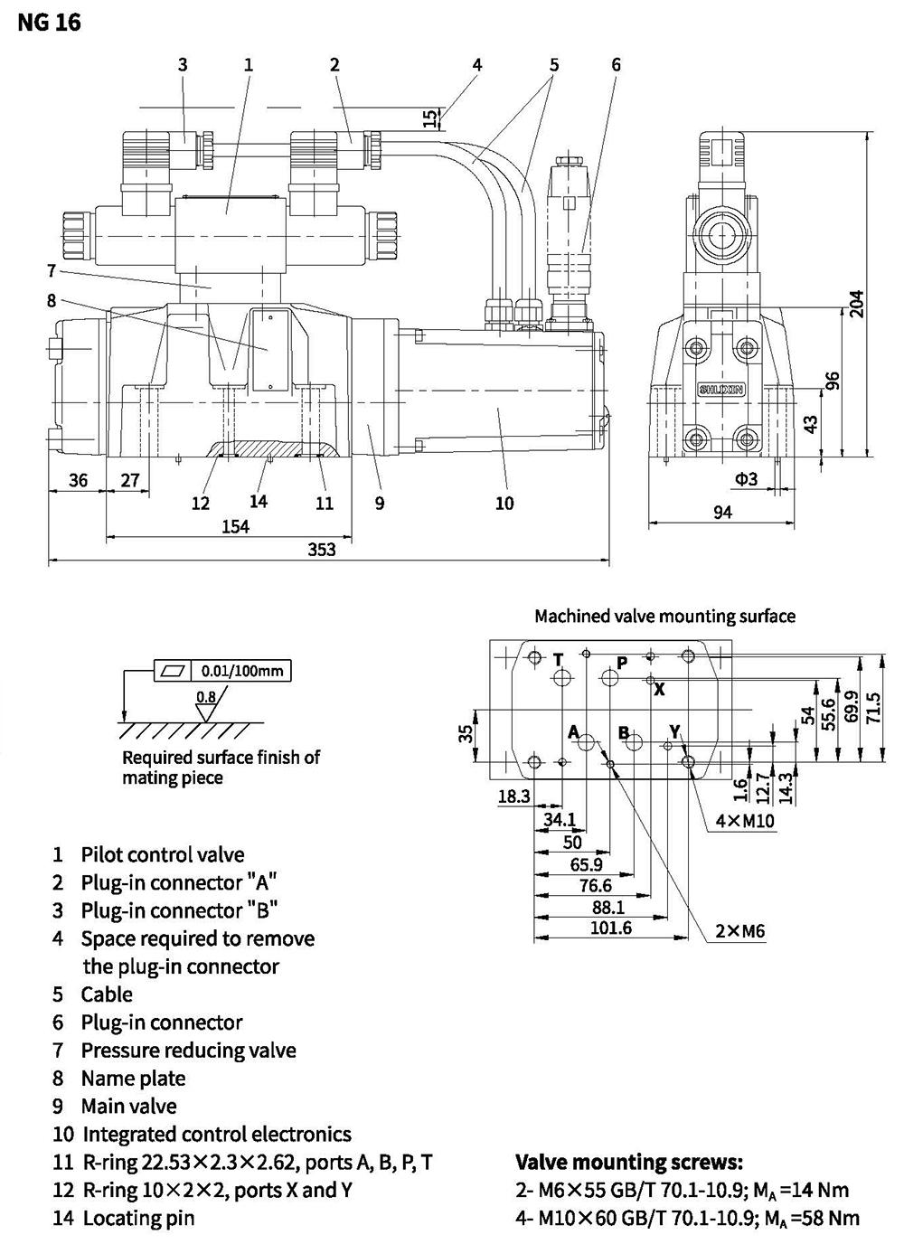
Unit dimensions
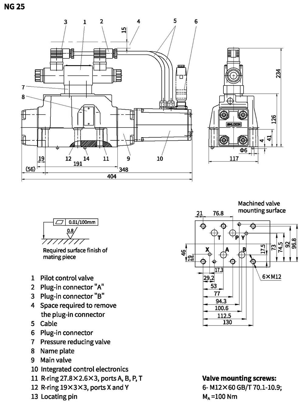
Unit dimensions
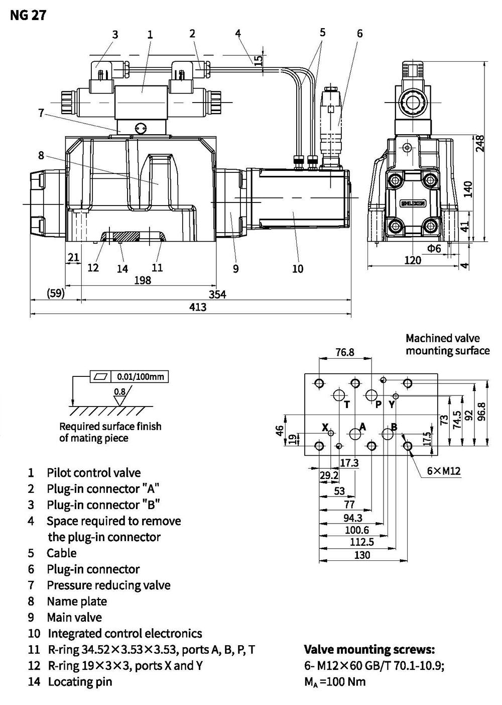
Unit dimensions
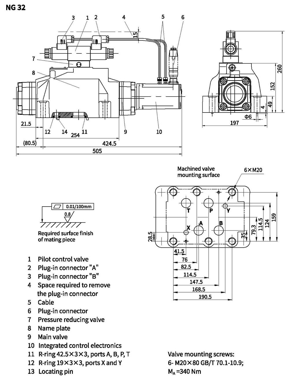
Unit dimensions