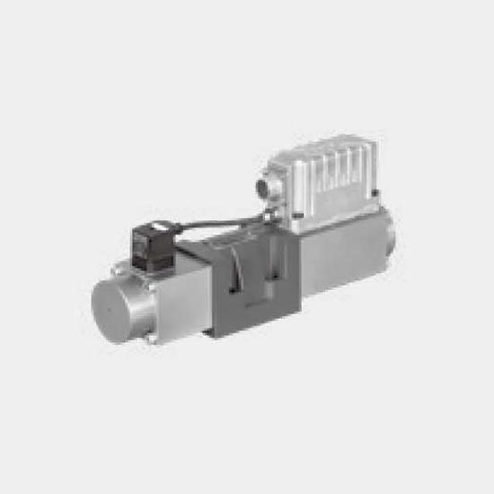
Function and configurationThe direct operated control valve 4WRMCEH10...L1X shows extremely high dynamics combined with high flow. It is the preferred choice for highest accuracy in positioning of hyd...
Product Detail
Function and configuration
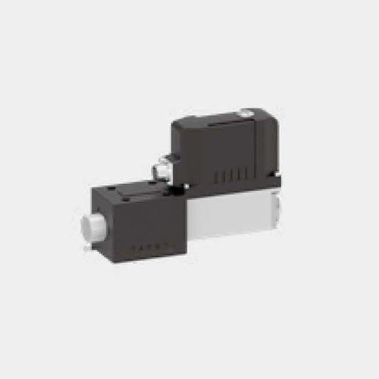
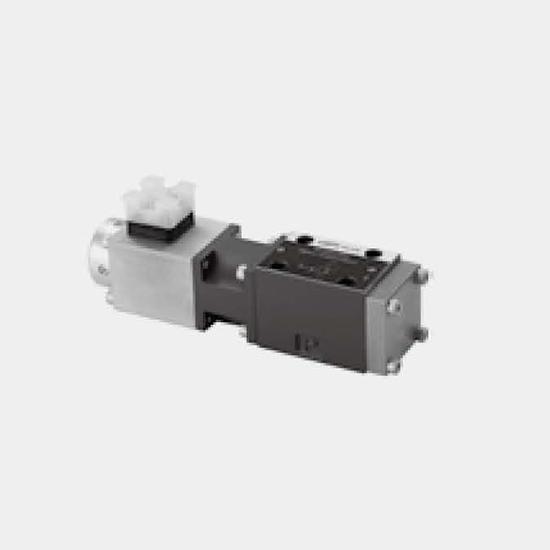
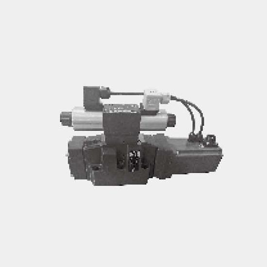
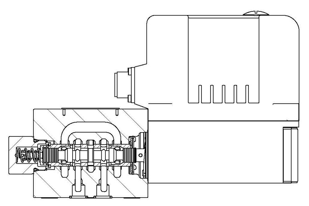
The direct operated control valve 4WRMCEH10...L1X shows extremely high dynamics combined with high flow. It is the preferred choice for highest accuracy in positioning of hydraulic axis and controlling of pressure and velocity. Driven by the voice coil motor actuator the valve reaches the frequency response of real servovalves. At power-down the spool moves in a defined position. All common input signals are available.
Ordering code
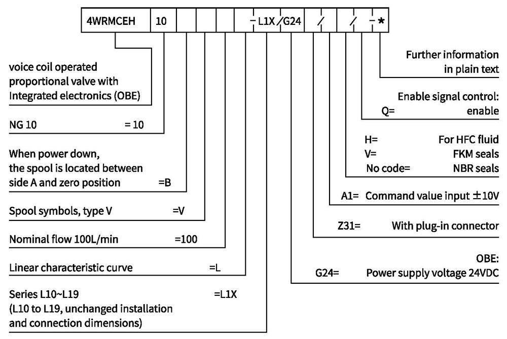
Symbols
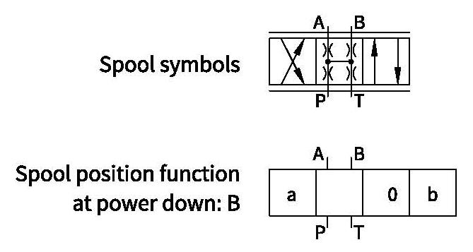
Technical data
| General | ||
| Size | 10 | |
| Weight | kg | 6.5 |
| Installation position | A ny, preferably horizontal | |
| Ambient temperature range | ℃ | -20 to+50 |
| Hydraulic (measured with HLP46, 9oll=40℃ ±5℃) | ||||
| Max. 1) operating pressures | -P orts A, B, SP | bar | 350 | |
| -Port T | internal drain | 35 | ||
| external drain | 250 | |||
| -Port Y | 35 | |||
| Rated flow at Δp = 35bar per control edge | L/min | 50,100 2) | ||
| Max.flow | L/min | 150 | ||
| Leakage at P= 100bar | mL/min | <400 (zerolap spool); <100 (overlap spool) | ||
| Hydraulic fluid | Mineral oil (HL, HLP) to DIN 51524 | |||
| Hydraulic fluid temperature range | ℃ | -20 to +60; NBR:-25 to+60 | ||
| Viscosity range | m㎡/s | 20 to 400; preferably 30 to 80 | ||
| Max.admissible degree of contamination of the hydraulic fluid, cleanliness class according to ISO 4406(c) | Class 18/16/13 | |||
| Hysteresis | % | <0.05 | ||
| Response sensitivity | % | <0.03 | ||
| Response time 0~100% step signal 3) | ms | <6 | ||
| Frequency response (±5 % signal) 3) | Hz | 200 (amplitude ratio-3dB), 200 (phase lag-0°) | ||
| Electric | |||
| Duty ratio | % | 100 | |
| Supply voltage/ripple | VDC | Direct voltage 22...30,electric shut-off at<19, ripple <5% effective, surge free | |
| Current consumption max. | A | 3.5 | |
| Pre-fusing | A | 4.0, medium lag | |
| Input signal: A1 | Voltage | V | -10...+10, ripple <0.01% effective, surge free |
| Impedance | kΩ | 100 | |
| Input signal: F1 | Current | m nA | +4···20, ripple <0.01%o effective, surge free, <3.6mA=disable,>3.8mA=enable |
| Impedance | Ω | <250 | |
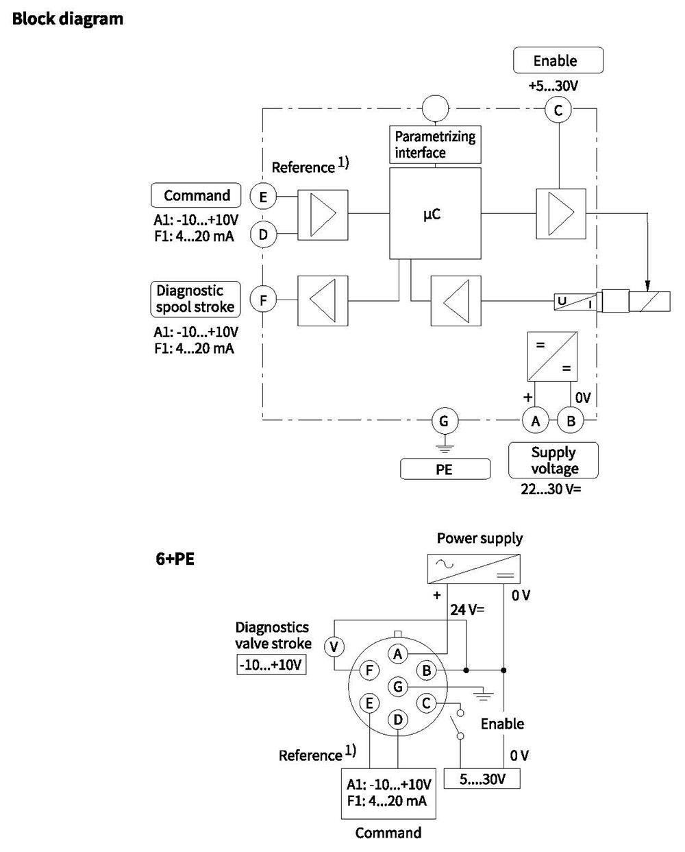
| Enable signal | V | 5...30, R1=9 kOhm | |
| Electrical connection | 6+PE,plug-in connector in accordance with DIN EN 175201-804 standard | ||
| Protection class of the valve according to EN60529 | Ip65 | ||
| EMC | EN 61000-6-2,EN 61000-6-4 | ||
Notes:
1) For applications with Pr>35 bar, the port Y has to be connected and the plug in the port Y has to be removed.
2) Flow rate for different Ap per control edge:Q=Qwom
3) Measured with load 100 bar pressure drop/two control edges.
Electrical connections
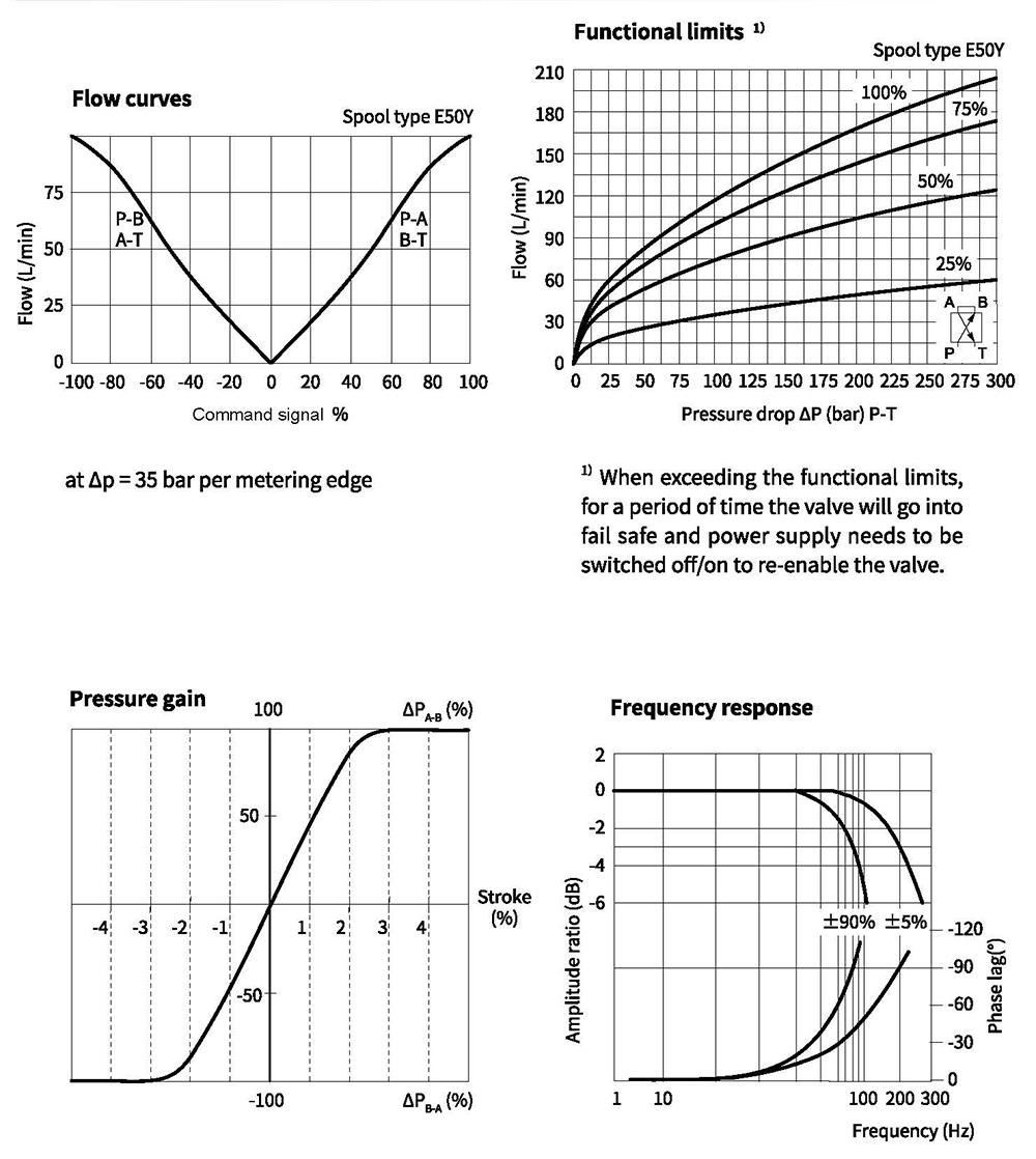
Characteristic curves(measured at AP=5bar, with HLP46, oil =50°C)
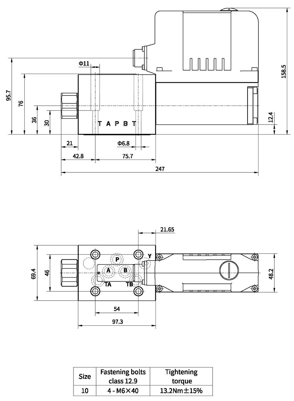
Unit dimensions