Technical dataWeight mApprox.0.15kgVoltage UDC 24V (-5%~+10%Power P30VAFuse wire Is1.2ATControl voltage UInput differential 0~+10VManual potentiometer input 0~+9VMin. load resistance for control vlolt...
Product Detail
Technical data
| Weight m | Approx.0.15kg |
| Voltage U | DC 24V (-5%~+10% |
| Power P | 30VA |
| Fuse wire Is | 1.2AT |
| Control voltage U | Input differential 0~+10V |
| Manual potentiometer input 0~+9V | |
| Min. load resistance for control vloltage R | 500Ω |
| Max. output current Imax | 800mA |
| Max. load resistance R | 30Ω |
| Pilot current I | 100mA |
| Vibration current frequency f | 200Hz |
| Ambient temperature t | 0~40℃ |
| Temperature drift | 0.5‰(max.current value)/℃ |
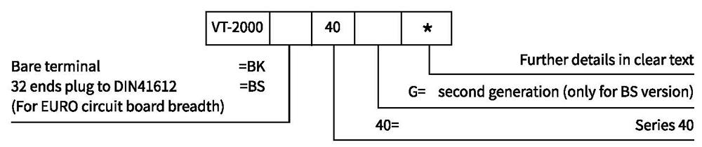
Ordering code
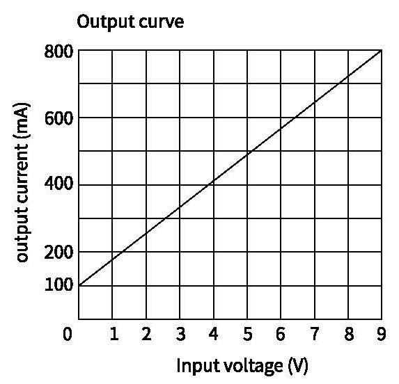
Characteristic curve
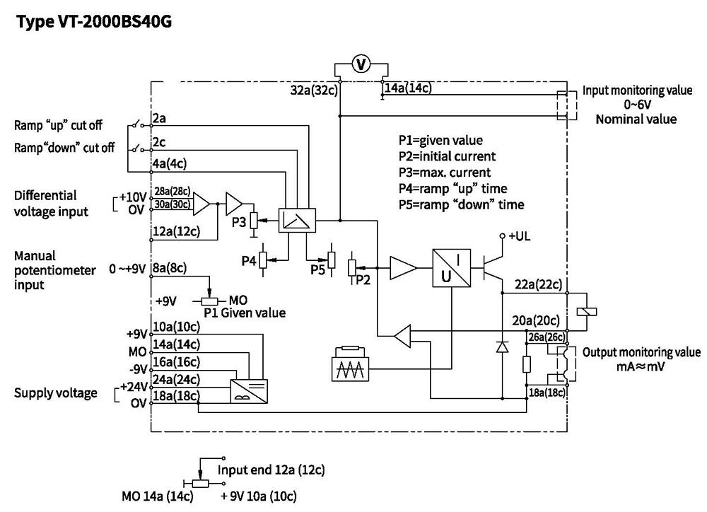
Wiring diagram of amplifier
Application specification
Type VT-2000BS40G
Principle chart of Hydro-electric proportional amplifier type VT-2000BS40G see Wiring Chart
20a (20c), 22a (22c) in the right of the dotted line, connects with proportional solenoid coil,
And 22a (22c) is the high electric potential and 20a(20c) is the low electric potential.
24a (24c), 18a (18c, 16a, 16c) in the left of the dotted line, connects with DC 24V power,
among them, 24a (24c) connects the positive pole, 18a (18c, 16a, 16c) connects the negative pole.
The controller's power shall be separate with the differential input power,
namely 30a (30c) can't connect the 14a (14c) and 18a (18c, 16a, 16c),
otherwise, it could be damage the controller.
Two controlling methods:
(1). manual control:
a: External potentiometer (provided by user themselves, suggesting to use one with resistance greater than 5K and smaller than 10K but smaller than 2K is not permitted; Power is not limited ),
one end connects 10a (10c) (+9), another end connects 14a (14c) (M0 is the measurement zero );
and the slide end connects 12a (12c). Input the voltage value 0~ +9 V into 12a (12c) end by adjusting the potentiometer, and 100~800mA square wave pulse current will proportionally appears from the proportional solenoid.
b: The controller has a built-in input potentiometer P1, the amplifier panel
(2). Automatic control:
Differential voltage signal from the programmable controller (PLC), function generator and so on inputs from 28a (28c), 30a (30c), and 28a (28c) connects high frequency, while 30a (30c) low frequency. Correspondingly appearing 100~800mA in the solenoid when the differential changes at range of 0~10V.
Notes: Don't make the 30a (30c) connected with the 14a (14c)(M0) or negative end 18a (18c), 16a (16c) of the DC24V power, namely the PLC and the proportional controller can't use one power or have mutual grounding.
When the requiring current is less than 800mA, it can limit the max. current by adjusting the P3 in the amplifier panel, e.g. input +9V to end 12, it can limit the output current 800mA into 600mA or other values by adjusting the potentiometer P3.
Two potentiometer P4 and P5 in the amplifier panel is respectively used for adjusting the time of ramp "up" and "down", and the adjustable time range is 0.2~5 seconds.
There is two pairs test holes, the 0~+6V test hole for monitoring the input voltage signal, mV ≈ mA hole for monitoring the output current and the mV measured by the voltage meter approx. equal the mA value in the solenoid.
Potentiometer P2 (initial current) on the panel is used for adjusting the pilot current with the range 0~400mA; and preset current is 100mA before dispatch from factory.
Note:
Other potentiometers on the panel have been adjusted before shipment from the factory, if you modify them, the performance parameter given by the manual will not be effective. This amplifier can be plugged in and off only under the electric breakaway.
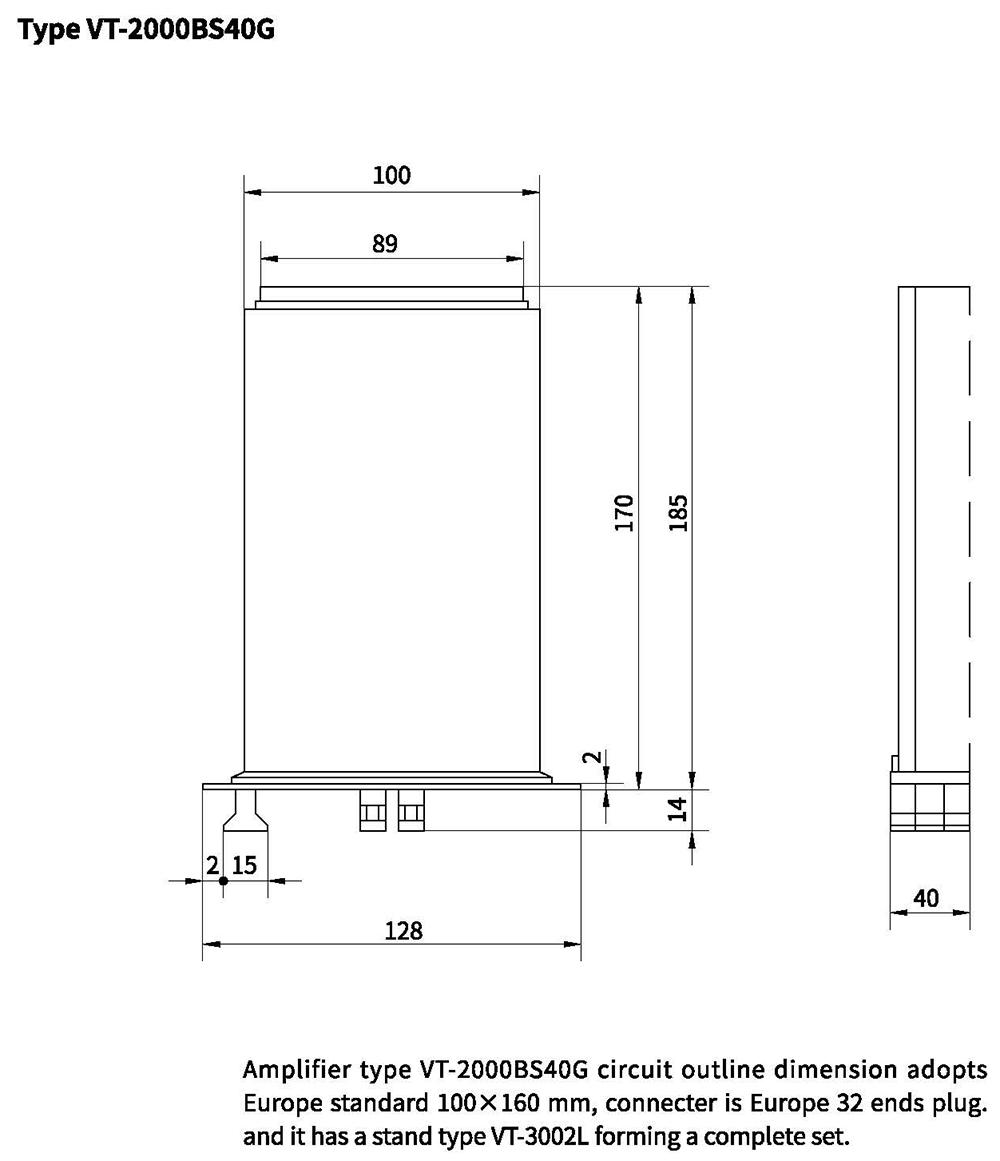
Outline dimension
Wiring diagram of amplifier
Application specification
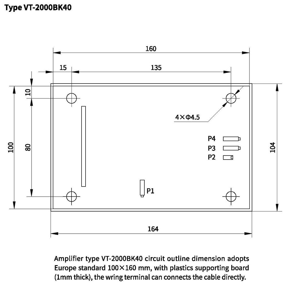
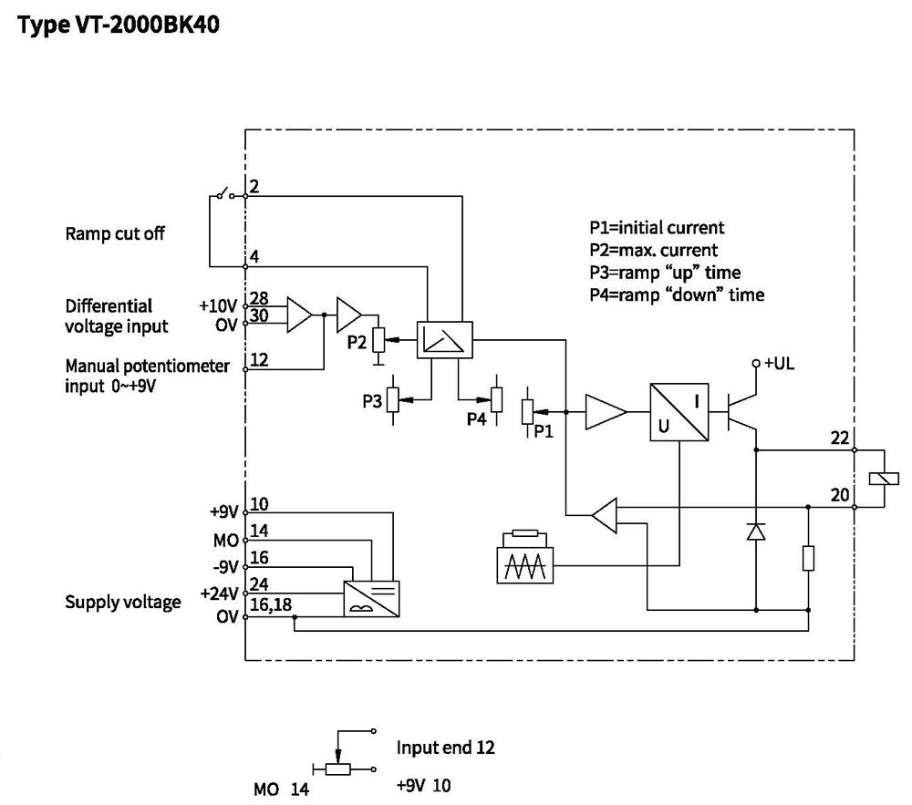
Type VT-2000BK40
Principle chart of Hydro-electrical proportional amplifier type VT-2000BK40 see Wiring Chart.
End 20 and 22 in the right of the dotted line, connects with proportional solenoid coil (22 is the high electric potential and 20 is the low electric potential.)
End 24, 18 (or 16) in the left of the dotted line, connects with DC 24V power, among them, 24 connects the positive pole, 18 or 16 connects the negative pole. The controller's power shall be separate with the differential input power, namely end 30 can't connect the 14 and 18 or 16, otherwise, it could be damage the controller.
Two controlling methods:
(1) Manual control:
External potentiometer (provided by user themselves, suggesting to use one with resistance greater than 5K and smaller than 10K but smaller than 2K is not permitted; Power is not limited), one end connects 10 (+9), another end connects 14 (M0 is the measurement zero); and the slide end connects 12. Input the voltage value 0~+9V into end12 by adjusting the potentiometer, and 100~800 mA square wave pulse current will proportionally appear from the proportional solenoid to actuate it.
(2) Automatic control:
Differential voltage signal from the programmable controller (PLC), function generator and so on inputs from end 28 and 30, among them, end 28 connects high frequency, while 30 low frequency. Correspondingly appearing 100~800mA in the solenoid when the differential changes at range of 0~10V.
Notes: Don't make the end 30 connected with the 14 (M0) or negative end 18, 16 of the DC24V power, namely the PLC and the proportional controller can't use one power or have mutual grounding.
When the requiring current is less than 800mA, it can limit the max. current by adjusting the P2 in the amplifier panel, e.g. input +9V to end 12, it can limit the output current 800mA into 600mA or other values by adjusting the potentiometer P2.
Two potentiometer P3 and P4 in the amplifier panel is respectively used for adjusting the time of ramp "up" and "down", and the Max. time of ramp is 5 seconds. If system needn't ramp time, 2 and 4 can be short-circuited.
Potentiometer P1 on the panel is used for adjusting the pilot current with the range 0~400mA; and preset current is 100mA before dispatch from factory.
Note:
Other potentiometers on the panel have been adjusted before shipment from factory, if you modify it, the performance parameter given by the manual will not be assured.
Outline dimension